5 Appendix
EDBC250SBC |1.1
l
ll
l
21
5 Appendix
5.1 Technical data (Overview)
5.1.1 System features
connected straight to module housing
assisted combi plug with mechanical ejector, 4 … 36
LED located next to the terminal
LED: bus state, module state, broken wire/excessive current
up to 32 digital I/Os on every module
20 per bus coupler (total max. power consumption:3A)
modules electrically insulated from one another and from the bus
2, Installation on an earthed top hat rail in the earthed
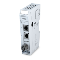
5.1.2 Safety bus coupler
EtherCAT 100Mbit/s 100 Base TX
connection to first Safety
integrated in side panel of module
 Loading...