The modular system
7
Mechanical installation
7.2
l
7.2-2
EDSPM-TXXX-3.0-04/2004
Stop!
Only plug the modules on the backplane bus or remove them if the
supply voltage is switched off!
#0
#1
#2
#n<33
_
4
3
2
1
CLACK!
60
40
epm-t055
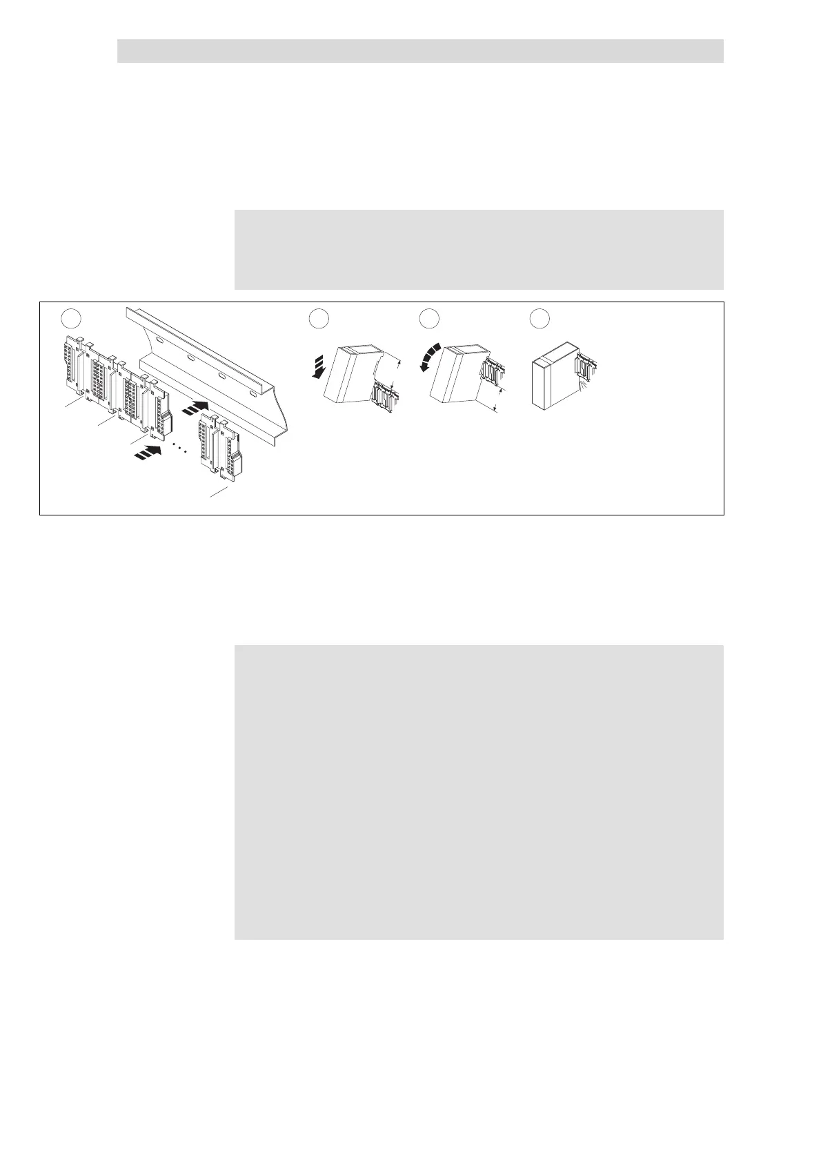
Fig. 7.2-2 Mounting the module on the DIN rail
c Mount the DIN rail to allow the module an installation clearance of min. 60 mm
at the top and min. 40 mm at the bottom.
Press backplane bus on to the DIN rail until it safely engages
d Lower the module on to the DIN rail at an angle of approx. 45 °
e Turnthemoduledownward
f Connection to the backplane bus is established once the module has audibly
engaged with the DIN rail.
Note!
z
The backplane bus is available in single (EPM-T910), double
(EPM-T911), quadruple (EPM-T912) and octuple (EPM-T913)
versions.
– In order to determine the number of slots, add a 1 to the
backplane bus versions you want to use, e. g.:
single
(EPM-T910)
+octuple
(EPM-T913)
+1=10slots.
z
The modules are always arranged from left to right and must
always start with the CAN gateway module.
z
Modules must always be plugged directly next to each other.
Free slots are not permissible since this would interrupt the
backplane bus.
z
A module is electrically connected only once it has audibly
engaged.
z
Slots to the right of the last module may remain unassigned.
z
The number of modules is limited to max. 32.
Mounting
 Loading...