11.5 Brake energy management
When braking electrical motors, the kinec energy of the drive train is fed back regeneravely
to the DC bus. This energy causes a DC-bus voltage boost. If the energy fed back is too high,
the inverter reports an error.
Several dierent strategies can serve to avoid DC-bus overvoltage:
•
Stopping the deceleraon ramp funcon generator when the acve voltage threshold for
the brake operaon is exceeded
•
Use of the "Inverter motor brake" funcon
•
Combinaon of the above named opons
Details
The voltage threshold for braking operaon results on the basis of the rated mains voltage set:
Rated mains voltage Voltage thresholds for braking operaon
Braking operaon on Braking operaon o
230 V DC 390 V DC 380 V
400 V DC 725 V DC 710 V
480 V DC 780 V DC 765 V
The voltage threshold for braking operaon can be reduced by 0 ... 100 V. The reducon
required must be set in 0x2541:003 (P706.03). However, the reducon must be made to such
an extent that the reduced voltage threshold is sll above the normal staonary DC-bus volt-
age.The acve voltage threshold for the braking operaon is displayed in 0x2541:002
(P706.02).
If the DC-bus voltage exceeds the voltage threshold for braking operaon, the braking method
selected in 0x2541:001 (P706.01) is applied.
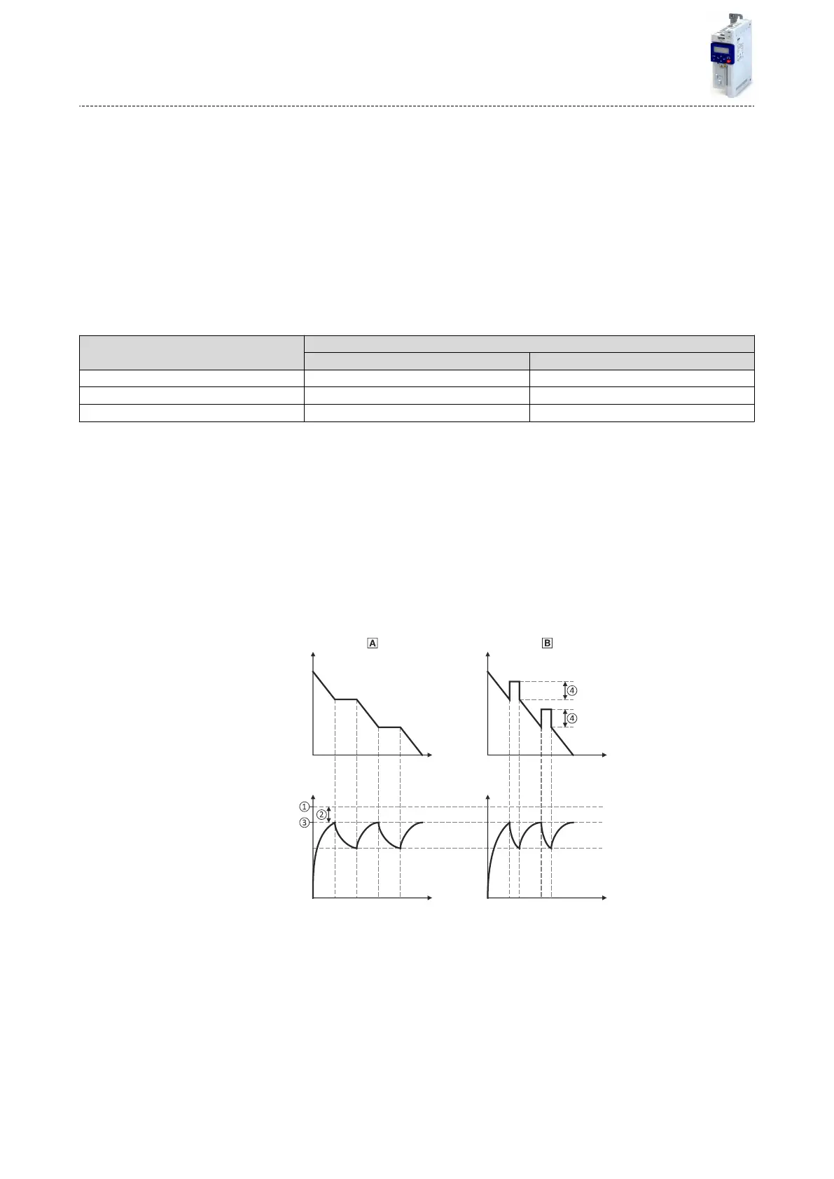
•
Stopping the deceleraon ramp funcon generator enables smoother deceleraon with
lower torque oscillaon.
•
The "Inverter motor brake" funcon allows for quick braking. For process-related reasons,
torque oscillaons may occur.
t t
t t
DC-bus voltage
during braking
Effective
frequency setpoint
①
Voltage threshold for braking operaon
0
Stopping the deceleraon ramp funcon generator ^ 275
②
Reduced threshold 0x2541:003 (P706.03)
1
Inverter motor brake ^ 276
③
Acve threshold 0x2541:002 (P706.02)
④
Addional frequency 0x2541:004 (P706.04)
Addional funcons
Brake energy management
274

 Loading...


