13 RG-SDMOD
Drive Control & Communication
5.1 Abbreviations
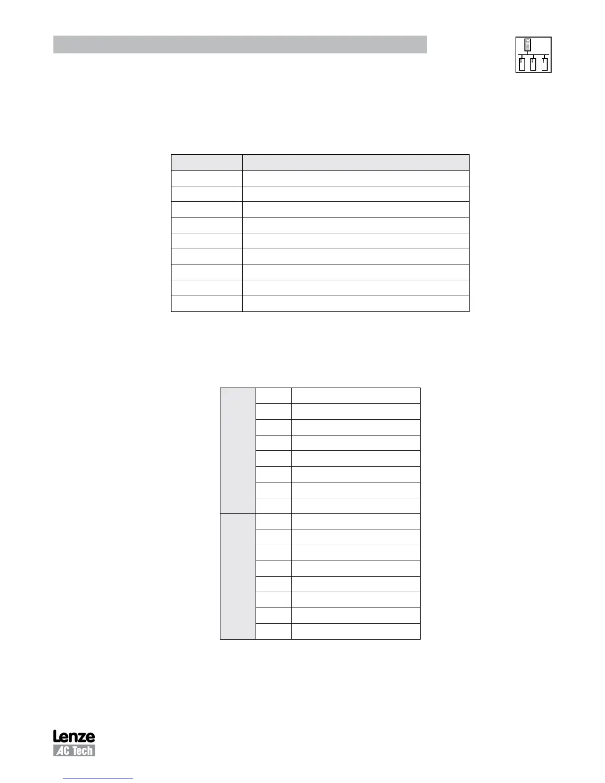
Table 7 lists the abbreviations used in Table 6
smd
Drive Control Registers:
Table 7: Abbreviations
Abbreviation Description
R Read
W Write
RS Response
SA Slave Address (typically 01 through F7 hex)
CRCH Cyclic Redundancy Check High byte
CRCL Cyclic Redundancy Check Low byte
DH Data High byte
DL Data Low byte
smd
#
smd
Register # (Modbus Register numbers are 1 larger)
5.2 Drive Control - Register #1
Table 8 illustrates the Data High Byte and Data Low Byte format of Register #1, Drive Control.
Table 8: Drive Control - Register #1
Data Low Byte
0 UPDATE BUFFERS
1 LOCK SECURITY
2 STOP DRIVE (COAST TO STOP)
3 START DRIVE
4 UNUSED
5 UNUSED
6 SET REVERSE
7 SET FORWARD
Data High Byte
8 SERIAL SPEED REFERENCE
9 LOCAL SPEED REFERENCE
10
11
12
13
14
15
The appropriate bit is set to 1. For example, to stop the drive bit two is set (send 0004H). To start the drive
send 0008H. Setting update buffers bit, enables to start the drive using downloaded data. Locking security
disables the serial drive control, the communications watchdog timer and prevents any further writing to
control or parameter registers.
Phone: 800.894.0412 - Fax: 888.723.4773 - Web: www.clrwtr.com - Email: info@clrwtr.com
 Loading...