NOTES:
• If using a non-Leviton Programmer/Remote, refer to the
Programmer/Remote instruction sheet.
• 4-Scene controllers incuded into a Z-Wave
®
network must be
updated after you have included all other devices.
• If using the VRCPG Install Checklist feature, go to step C.
A) If using a Leviton Z-Wave
®
Programmer/Remote, Cat. No. VRCPG,
press the Menu button and scroll down to System Setup. Press
the center button to select System Setup Menu. Choose Advanced
Settings. Press the center button to select Network. Press the center
button to <Include Node>.
B) If using VRCPG Programmer/Remote, you will be prompted to place
4-Scene controller into programming mode.
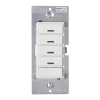
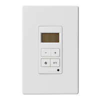
C) To access Program mode, press and hold
buttons 1 and 3 (refer to figure). Wait
5 seconds until the LED turns Amber.
Release the buttons and the LED will blink
Amber. You are now in Programming mode.
NOTE: If the LED on the 4-scene controller
turns solid Red while including, there has
been a communication error.
D) While standing close to the 4-Scene
controller (approximately 1 ft.), press the
center button on the Programmer/Remote
to <Include> device in the network.
NOTE: If the LED on the 4-scene controller
turns solid Red while including, there has
been a communication error.
NOTE: Only one device may be included at any time.
E) The Primary Programmer/Remote will assign a Home ID, Node ID,
and Name for this device.
NOTE: This information will be stored in the Programmer/Remote to
be used for future reference.
NOTE: You may name or edit your device at this time.
F) The 4-Scene controller is now installed in the network.
WARNINGS AND CAUTIONS:
• ON/OFF LED for remote load status.
• To be installed and/or used in accordance with appropriate electrical codes and regulations.
• If you are unsure about any part of these instructions, consult a qualified electrician.
• Vizia RF +
TM
VRCS4 controller does not control the load, but provides scene applications to operate with Vizia RF +
TM
dimmers/switches.
• Recommended minimum wall box depth is 2-1/2".
WARNINGS AND CAUTIONS:
• Can call up four (4) scene ON/OFF with advanced Programming Remote (see VRCPG).
• Disconnect power at circuit breaker or fuse when servicing, installing or removing fixture.
• Use this device only with copper or copper clad wire. With aluminum wire use only devices marked CO/ALR or CU/AL.
4-Scene Controller
Cat. No. VRCS4-1L
120VAC, 60Hz
INSTALLATION INSTRUCTIONS
DI-000-VRCS4-02A-X1
Tools needed to install your 4-Scene Controller:
Slotted/Phillips Screwdriver Electrical Tape Pliers
Pencil Cutters Ruler
ONOFF
ONOFF
ONOFF
ONOFF
ONOFF
ONOFF
ONOFFONOFF
ONOFF
ONOFF
ONOFF
ONOFF
WARNING: TO AVOID FIRE, SHOCK OR DEATH; TURN
OFF POWER at circuit breaker or fuse and test that power is off
before wiring!
Step 1
Step 3
Preparing and connecting wires:
This 4-Scene controller can be wired using side wire terminal
screws or through backwire openings. Choose appropriate wire
stripping specifications accordingly.
• Make sure that the ends of the wires from the wall box are
straight (cut if necessary).
5/8"
(1.6 cm)
Strip Gage
(measure bare
wire here)
Cut
(if necessary)
Back Wire (either hole may be used)
Back wire openings use #14-12 AWG
solid wire copper only.
Side Wire Connection
Side wire terminals accept
#14 AWG solid wire copper only.
WIRING 4-SCENE CONTROLLER:
Connect wires per WIRING DIAGRAM as follows:
• Green or bare copper wire in wall box to Green terminal screw.
• Line Hot wall box wire to terminal screw marked "BK".
• Line Neutral wall box wire to terminal screw marked "WH".
Wiring Application:
Hot (Blac k)
Neutral (White)
Line
120VAC , 60Hz
BKWH
Green
Ground
4-Scene Contr oller
1. Line (Hot)
2. Neutral
3. Ground
Identifying your wiring application (most common):
NOTE: If the wiring in your wall box does not resemble this
configuration, consult a qualified electrician.
Step 2
INTRODUCTION
Leviton’s Vizia RF +
TM
components are designed to communicate
with each other via Radio Frequency (RF) to provide remote control
of your lighting. Using RF technology allows Leviton to provide the
greatest signal integrity possible. Each module in Leviton’s Vizia RF +
TM
component line is a Z-Wave
®
enabled device. In a Z-Wave
®
network,
each device is designed to act as a router. These routers will re-transmit
the RF signal from one device to another until the intended device is
reached. This ensures that the signal is received by its intended device
by routing the signal around obstacles and radio dead spots. The
4-Scene Controller is compatible with any Z-Wave
®
enabled network,
regardless of the manufacturer and can also be used with other devices
displaying the Z-Wave
®
logo.
• This is a Z-Wave
®
Controller
• Scene control without traveler wires
• Can call 4 scenes
• ON/OFF LED
• Two way communication
• RF reliability
• Ease of installation – No new wiring
• Compatible with other Z-Wave
®
enabled devices
FEATURES
Step 8
Including 4-Scene Controller into Z-Wave
®
Network:
Changing the color of your 4-Scene Controller:
Your 4-Scene controller includes three color options. The controller ships
with the White frame attached. To change color of frame, proceed as
follows:
Line up tabs
and press in
side to attach
Push in
side at tab
to release
After frame is removed, remove existing push buttons and replace them
with desired color change push buttons. To change the DIM/BRIGHT
button, before mounting frame, press out DIM/BRIGHT button (bottom)
from back of frame and press in from front of frame new DIM/BRIGHT
button. To make IR capable, replace with a DIM/BRIGHT button that has
the IR window.
INSTALLING YOUR 4-SCENE CONTROLLER
NOTE: Use check boxes when Steps are completed.
• Position all wires to provide room in
outlet wall box for device.
• Ensure that the word “TOP” is facing up
on device strap.
• Partially screw in mounting screws in
wall box mounting holes.
NOTE: Dress wires with a bend as
shown in diagram in order to relieve
stress when mounting device.
• Restore power at circuit breaker or fuse.
• LED should turn ON.
If LED does not turn ON, refer to the
TROUBLESHOOTING section.
Testing your 4-Scene Controller prior to
mounting in wall box:
Step 5
Restore Power:
Restore power at circuit breaker or fuse.
Installation is complete.
Installation may now be completed by
tightening mounting screws into wall box.
Attach wallplate.
4-Scene Controller Mounting:
TURN OFF POWER AT CIRCUIT BREAKER OR FUSE.
Step 6
Step 7