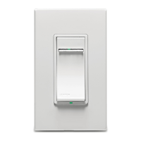
Single Pole (One location) or 3-Way (Multi-location)
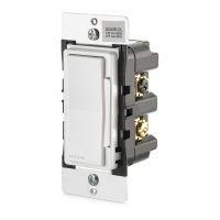
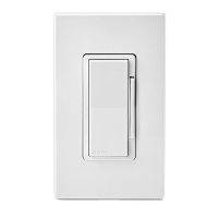
Magnetic Low-Voltage Dimmer
Cat. No. VZM1
Ø
-1L, 1000VA (Lighted)
120VAC, 60Hz
INSTALLATION INSTRUCTIONS
DI-000-VZM10-02C
ONOFF
ONOFF
ONOFF
ONOFF
ONOFF
ONOFF
ONOFFONOFF
ONOFF
ONOFF
ONOFF
ONOFF
3-Way
1. Line or Load
(See IMPORTANT note)
2.
Neutral
3.
Ground
4.
First Traveler – note color
5.
Second Traveler – note color
NOTE: For matching remote w/LEDs installation,
the First Traveler becomes Line Hot.
WIRING DIMMER:
Connect wires per WIRING DIAGRAM as follows:
WARNING: CONNECT A MAGNETIC LOW-VOLTAGE
DIMMER ONLY TO THE PRIMARY (HIGH-VOLTAGE) SIDE
OF A MAGNETIC LOW-VOLTAGE TRANSFORMER.
• Green or bare copper wire in wall box to Green dimmer
lead.
• Line Hot wall box wire to Black dimmer lead.
• Load wall box wire to Red dimmer lead.
• Yellow/Red dimmer lead should have Red insulation label
affixed. NOTE: If insulating label is not affixed to Yellow/Red
dimmer lead, use electrical tape to cover.
• Proceed to Step 5.
Hot (Black)
Neutral (White)
Load
Dimmer
Black
Black
White
Red
Green
Ground
Line
120VAC, 60Hz
Yellow/Red
(PRIMARY SIDE OF
MAGNETIC LOW-VOLTAGE
TRANSFORMER)
}
Insulating
Label
4
3
2
1
Insulating Label:
This wire is used in 3-way installations only.
For single pole installations, do not remove this
insulating label.
Black
Green
Red
Yellow/Red
Dimmer
WARNINGS AND CAUTIONS:
• To be installed and/or used in accordance with appropriate electrical codes and regulations.
• If you are unsure about any part of these instructions, consult a qualified electrician.
• To avoid overheating and possible damage to this device and other equipment, do not install to control a receptacle, fluorescent lighting, a motor- or a transformer-
operated appliance.
• Use with magnetic low-voltage transformers, incandescent, or 120V halogen fixtures only. Use a Leviton electronic low-voltage dimmer to control electronic
(solid state) low-voltage transformers.
• When magnetic low-voltage circuits are operated at a dim level, with all lamps inoperative, excess current may flow through the transformer. To avoid possible
transformer failure due to overcurrent, use a transformer that incorporates thermal protection or a fuse at the primary windings.
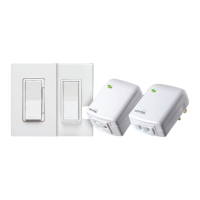
• Vizia™ dimmers are not compatible with standard 3-way or 4-way switches. They must be used with compatible Vizia™ remotes for multi-location dimming.
WARNINGS AND CAUTIONS:
• Use only one (1) Vizia™ dimmer in a multi-location circuit with up to 9 coordinating remotes without LEDs or up to 4 matching remotes with LEDs.
The remote(s) will turn the light on at the brightness level selected at the dimmer.
• Total minimum load must exceed 40W.
• Dimmer may feel warm to the touch during normal operation.
• Recommended minimum wall box depth is 2-1/2”.
• Maximum wire length from dimmer to all installed remotes cannot exceed 300 ft.
• Disconnect power at circuit breaker or fuse when servicing, installing or removing fixture.
• Use this device only with copper or copper clad wire. With aluminum wire use only devices marked CO/ALR or CU/AL.
Single-Pole
1. Line (Hot)
2. Neutral
3.
Ground
4.
Load
INSTALLING YOUR DIMMER
NOTE: Use check boxes when Steps are completed.
√
3-Way Wiring with Coordinating Dimming or
Switching Remote (no LEDs) Application:
BK
YL/R
D
R
D
4
3
2
5
Black
Green
Red
Yellow/Red
1
Coordinating Remote
2
4
3
5
1
Dimmer
WIRING DIMMER:
Connect wires per WIRING DIAGRAM as follows:
WARNING: FOR MAGNETIC LOW-VOLTAGE APPLICATIONS, CONNECT
DIMMER ONLY TO THE PRIMARY (HIGH-VOLTAGE) SIDE OF A
MAGNETIC LOW-VOLTAGE TRANSFORMER.
NOTE: When using the coordinating remote without LEDs, the dimmer can
be installed on either the Line or Load side of the 3-way circuit.
NOTE: Maximum wire length from dimmer to all installed remotes cannot
exceed 300 ft.
• Green or bare copper wire in wall box to Green dimmer lead.
• Line Hot (common) wall box wire identified (tagged) when removing old
switch to Black dimmer lead.
• First Traveler wall box wire to Red dimmer lead (note wire color). This
traveler from the dimmer must go to the terminal screw on the remote
marked “RD”.
• Remove Red insulating label from Yellow/Red dimmer lead.
• Second Traveler wall box wire to Yellow/Red dimmer lead (note wire
color). This traveler from the dimmer must go to the terminal screw on the
remote marked “YL/RD”.
Hot (Black)
Neutral (White)
Load
Dimmer
Coordinating Remote (no LEDs)
YL/RD
Yellow/
Red
RD
WH
Red
Black
BK
Black
Do not use for
incandescent
applications.
White
Line
120VAC, 60Hz
Green
Ground
Green
Ground
(PRIMARY SIDE OF
MAGNETIC LOW-VOLTAGE
TRANSFORMER)
}
(Coordinating Dimming Remote Depicted)
IMPORTANT: For 3-Way applications, note that one of the screw
terminals from the old switch being removed will usually be a
different color (Black) or labeled Common. Tag that wire with
electrical tape and identify as the common (Line or Load) in both the
dimmer wall box and remote wall box.
Step 2 cont’d
• Pull off pre-cut insulation from dimmer leads.
• Make sure that the ends of the wires from the wall box are
straight (cut if necessary).
• Remove insulation from each wire in the wall box as shown.
•
For Single-Pole Application, go to Step 4a.
• For 3-Way Coordinating Remote (no LEDs) Application, go
to Step 4b.
• For 3-Way Matching Remote (with LEDs) Application, go
to Step 4c.
WIRE NUT / # OF CONDUCTOR
COMBINATION CHART
1- #12 w/ 1 to 3 #14, #16 or #18
2- #12 w/ 1 or 2 #16 or #18
1- #14 w/ 1 to 4 #16 or #18
2- #14 w/ 1 to 3 #16 or #18
For non-standard wiring applications, refer
to Wire Nut and Conductor Size Chart
Tools needed to install your Dimmer
Slotted/Phillips Screwdriver Electrical Tape
Pliers Pencil
Cutters Ruler
Push in side at
tab to release
Line up tabs and press
in side to attach
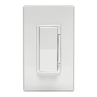
Changing the color of your Dimmer:
Your Dimmer includes three color options. The Dimmer ships with
the White frame attached. To change color of frame, proceed as
follows:
If installing Dimmer in a single device application, proceed with
the INSTALLING YOUR DIMMER section. If installing Dimmer in
a multi-device application, proceed as follows:
MULTI-DEVICE APPLICATION
In multi-dimmer installations, the side sections of the mounting
strap may require removal. Use pliers to carefully bend side
sections back and forth until they break off.
Installing Dimmer by itself or with other devices
MAXIMUM LOAD PER DIMMER FOR MULTI-DEVICE
Load
Mag LV
1000VA
Single
800VA
Two Devices
650VA
More than
2 Devices
MAXIMUM BULB WATTAGE
Low-voltage dimmers are rated in Volt-Amps (VA). The maximum bulb
wattage is determined by the efficiency of the transformer in the low-
voltage lighting system. Transformer efficiencies will vary from different
manufacturers; consider 75% efficient as average. Use the chart to
determine maximum bulb wattage for typical transformer efficiency ratings.
WARNING: TO AVOID FIRE, SHOCK, OR DEATH;
TURN OFF POWER
at circuit breaker or fuse and test
that power is off before wiring!
Step 2
Identifying your wiring application
(most common):
NOTE: If the wiring in the wall box does not resemble any
of these configurations, consult a qualified electrician.
Step 1
MAXIMUM BULB WATTAGE AT 75% EFFICIENCY
Rating
1000VA 750W
Single
600W
Two Gang
525W
More than
2 Gang
Strip Gage
(measure bare
wire here or use
gage on back of
the dimmer)
Preparing and connecting wires:
Step 3
5/8”
(1.6 cm)
Single-Pole Wiring Application:
Step 4a Step 4b
Typically, removal of the side sections in multi-dimmer
installations requires a reduction of the dimmer’s capacity. Refer
to the chart for maximum load per dimmer.
Remove
all inner
side
sections
Do not
remove
outer
side
sections
Bend back and
forth to remove
side section