Quick Start Guide
DVI-HDCP-OPTM-TX90
DVI-HDCP-OPTM-RX90
DVI-HDCP-OPTS-TX90
DVI-HDCP-OPTS-RX90
Further Information
The Product Brief of this appliance is available on www.lightware.com.
See the Downloads section on the dedicated product page.
Contact Us
sales@lightware.com
+36 1 255 3800
support@lightware.com
+36 1 255 3810
Lightware Visual Engineering LLC.
Peterdy 15, Budapest H-1071, Hungary
Doc. ver.: 3.1
19200159
Important Safety Instructions
Please read the supplied safety instruction
document before using the product and
keep it available for future reference.
CAUTION - The use of controls or adjustments or any performance of procedures
other than those specied herein may result in hazardous radiation exposure.
Introduction
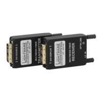
OPTM series
Lightware’s DVI-HDCP-OPTM-TX90 and DVI-HDCP-OPTM-RX90 pair is a DVI-D ber
transmitter and receiver set for up to 240 m (in case of OM2/OM3/OM4 cable) distance
transmission.
Using Single Fiber Technology the DVI-D signal with HDCP encryption is transmitted over
only one multimode 50/125 (or 62.5/125) ber core. Sources and display devices are
galvanically isolated against ground loops and hum effects, and no delay occurs in the signal,
the video image is transported without any frame latency.
OPTS series
The DVI-HDCP-OPTS-TX90 and DVI-HDCP-OPTS-RX90 pair is a DVI-D ber transmitter
and receiver set for up to 10 km (in case of OS2 cable) distance transmission.
Using Single Fiber Technology the DVI-D signal with HDCP encryption is transmitted over
only one single mode 9/125 ber core. Sources and display devices are galvanically isolated
against ground loops and hum effects, and no delay occurs in the signal, the video image is
transported without any frame latency.
Box Contents
Extender unit 5V DC power adaptor
with interchangeable plugs
USB cable with
micro USB plug
Safety and Warranty Info,
Quick Start Guide
1
DVI-D input plug
(transmitter)
DVI-D (single link) plug for receiving the DVI-D/HDMI input
signal from the source device.
2
Status LED Indicates the current status of the transmitted or received
optical signal.
FAST BLINKING The booting up procedure is in progress.
SLOW BLINKING No ber optical communication between TX and
RX devices.
ON The ber link is established successfully
between TX and RX.
Maximum Extension Distances
Singlemode (OPTS) Multimode (OPTM)
OS1 OS2
OM1 OM2 OM3 OM4
(62.5/125) (50/125) (50/125) (50/125)
For all resolution 5000 m 10000 m
Not
supported
240 m
Top View - Transmitter (TX)
Top View - Receiver (RX)
3
USB micro-B
connector
USB micro-B connector is for the external powering of the
extender.
4
LC out connector
(transmitter)
LC ber optical connector for multimode ber output.
5
DVI-D output
plug (receiver)
DVI-D (single link) plug for transmitting the DVI-D/HDMI
output signal to the sink device.
6
LC in connector
(receiver)
LC ber optical connector for multimode ber input.
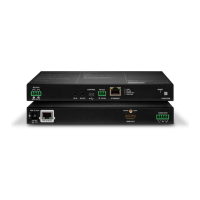
Rear View - Transmitter (TX) and Receiver (RX)
Connecting Steps
Follow the installation steps to connect the extenders between the source and sink devices:
Connect the multimode (in the case of OPTM) or the singlemode (in the
case of OPTS) fiber optical cable to the LC IN connector of the receiver.
Connect the DVI-D plug of the receiver to the input port of the sink device
(e.g. Projector). The extender reads the EDID from the display (projector,
monitor, etc), and outputs the video signal according to the set resolution.
Fasten the extender with the mounting screws.
Power on the receiver by choosing one of the powering options below:
Connect the USB plug of the power adaptor to the micro USB
connector of the receiver.
Connect the provided USB-A - USB micro-B cable between the
extender and the sink device.
Connect the multimode (in the case of OPTM) or the singlemode (in the
case of OPTS) fiber optical cable to the LC OUT connector of the transmitter.
Connect the DVI-D plug of the transmitter to the output port of the source
device (e.g. PC). Fasten the extender with the mounting screws.
Finally power on the transmitter by choosing one of the powering options below:
Connect the USB plug of the power adaptor to the micro USB
connector of the transmitter.
Connect the provided USB-A - USB micro-B cable between the
extender and the source device.
If the DVI source device is able to provide enough 5V DC current
(500mA), there is no need for external 5V DC power. The extender is
powered immediately when the source device is switched on.
Check the Status LED. When the connection has been made successful, the
blue LEDs on the transmitter and receiver will appear solid (not blinking).
It is not recommended to power on the devices before the nal step.
Important Safety Instructions
Please read and keep the information in the attached safety instructions supplied with the
product before starting using the device.
Safety Symbols Legend
Symbol Description
Caution
Laser radiation
WARNING
To prevent injury, the apparatus is recommended to securely attach to the oor/wall or
mount in accordance with the installation instructions. The apparatus shall not be exposed
to dripping or splashing and that no objects lled with liquids, such as vases, shall be placed
on the apparatus. No naked ame sources, such as lighted candles, should be placed on the
apparatus.
WEEE ( Waste Electrical & Electronic Equipment )
Correct Disposal of This Product
This marking shown on the product or its literature, indicates that it
should not be disposed with other household wastes at the end of its
working life. To prevent possible harm to the environment or human
health from, uncontrolled waste disposal, please separate this from
other types of wastes and recycle it responsibly to promote the
sustainable reuse of material resources.
Household users should contact either the retailer where they purchased, this product,
or their local government ofce, for details of where and how they can take this item for
environmentally safe recycling.
Business users should contact their supplier and check the terms and conditions of the
purchase contract. This product should not be mixed with other commercial wastes for
disposal.
DVI-HDCP-OPT-90 series
DVI-HDCP-OPT-90 series
PC Projector
Power adaptor
OPTM
OPTS
Power
DVI-D
DVI-D
DVI-HDCP-OPTS-RX90
S/N: 7A000942
DVI-HDCP-OPTS-TX90
S/N: 7A000941
364
Safety and
Warranty
Info
Quick
Start
Guide
CLASS 1 LASER PRODUCT