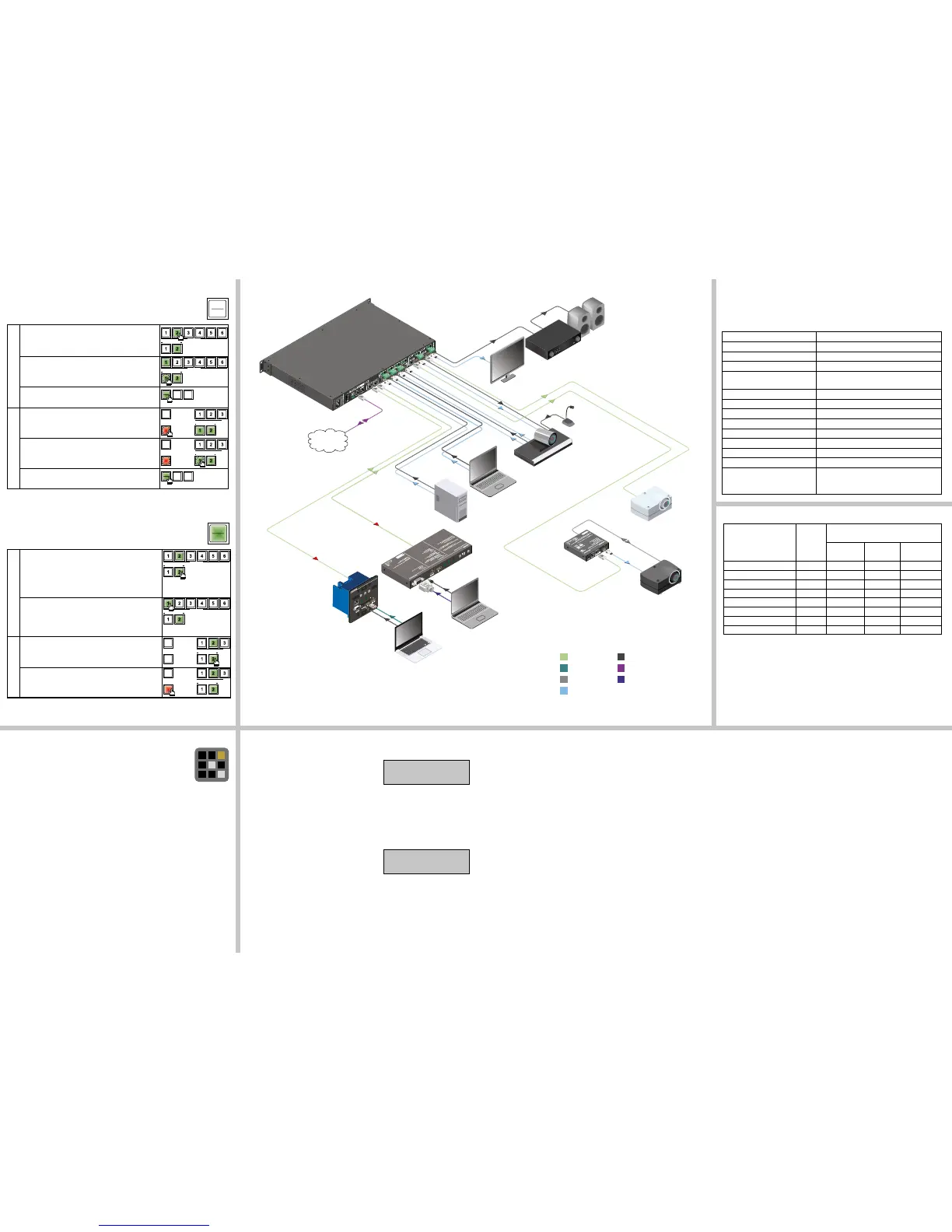
Maximum twisted pair distances
Resolution
Pixel
clock rate
Cable lengths
(Auto / Long reach TPS mode)
CAT5e
AWG24
CAT7
AWG26
CAT7
AWG23
1024x768@60Hz 65 MHz 100 m / 130 m* 90 m / 120 m* 120 m / 170 m*
1280x720p@60Hz 73.8 MHz 100 m / 130 m* 90 m / 120 m* 120 m / 170 m*
1920x1080p@60Hz (24bpp) 148.5 MHz 100 m / 130 m* 90 m / 120 m* 120 m / 170 m*
1920x1200@60Hz 152.9 MHz 100 m / NA 90 m / NA 120 m / NA
1600x1200@60Hz 162 MHz 100 m / NA 90 m / NA 120 m / NA
1920x1080@60Hz (36bpp) 223 MHz 70 m / NA 70 m / NA 100 m / NA
3840x2160@30Hz UHD 297 MHz 70 m / NA 70 m / NA 100 m / NA
4096x2160@30Hz 4K 297 MHz 70 m / NA 70 m / NA 100 m / NA
* Long reach TPS mode supports pixel clock frequencies up to 148.5 MHz.
Above values are valid when the connected extenders are powered by a local adaptor;
distances may decrease depending on the powering mode (local or remote) and cable
quality.
CAT7 SFTP AWG23 cable is always recommended.
Factory default settings
The settings and parameters can be set to factory default as follows:
1. Navigate to Settings / Fact. defaults submenu and press the enter.
2. Press the enter button to load the factory default settings, which are the followings:
IP address (static) 192.168.0.100
Subnet mask 255.255.255.0
Static gateway 192.168.0.1
DHCP disabled
TCP/IP port no. for LW2 / LW3
control protocol
10001 / 6107
Crosspoint setting HDMI I3 on O1 and O3, HDMI I4 on O2 and O4
Audio source embedded audio
Emulated EDID F47 - Factory (1920x1080@60Hz HDMI)
Autoselect disabled
Output TPS mode auto
PoE feature (on TPS ports) enabled
RS-232 mode and protocol pass-through, LW2 protocol
RS-232 port setting 57600 BAUD, 8, N, 1
RS-232 command injection port
number (Local / TPSIN1 / TPSIN2 /
TPSOUT1 / TPSOUT2)
8001 / 8002 / 8003 / 8004 / 8005
Network settings on the front panel
Setting a dynamic IP address
1. Navigate to Settings / Network / DHCP submenu
and press the enter button.
2. To change the setting, press the enter button and
use the up and down buttons to toggle between
the options; set to Enabled.
3. Press the enter button to save changes.
4. Press the escape button twice to navigate out from the submenu. You will be prompted
to apply settings; press the enter button.
Setting a static IP address
1. Disable the DHCP setting as described above.
2. Navigate to Settings / Network / IP Address
submenu and press the enter button.
3. To change the numbers press the enter button.
4. Use the left and right buttons to place the cursor
to the desired number; set the numbers by the up and down buttons.
5. Press the enter button to save changes.
6. Press the escape button twice to navigate out from the submenu. You will be prompted
to apply settings – press the enter button.
Typical application
Software control – Using Lightware Device Controller (LDC)
The device can be controlled from a computer using the Lightware Device
Controller software. The application is available at www.lightware.eu
(Support / Downloads section), install it on a Windows PC or a Mac OS X
and connect to the device. The following ways are available to connect to
the device directly:
Local USB port
Connect a USB cable (with mini B-type connector) between the matrix and the computer
and start the LDC. The device is displayed under the USB devices section; press Connect.
Local RS-232 port
Connect a serial cable between the matrix and the computer and start the LDC. Press
the Query button of the connected COM port to list the device and press Connect. See
the Factory default settings table for the RS-232 port parameters. The local RS-232
port settings are available in the front panel menu. Navigate to Settings / Control RS232
submenu. The following parameters can be set: Baud rate, Data Bits, Stop Bits and Parity.
LAN port
Connect the supplied LAN crosslink cable between the matrix and the computer for direct
connection or connect to an Ethernet. The default network settings are listed in above table
which can be changed via the front panel menu.
¹IP Address:
192.168.002.2½
¹DHCP:
Disabled ½
Switching operations
1. First press and release the desired source button.
The pressed source button and all destination buttons
which are currently connected to the source lights up.
SOURCES
DESTINATIONS
2. Press and release the desired destination buttons
which have to be (dis)connected to/from the selected
source. The preselected destination buttons will blink.
SOURCES
DESTINATIONS
3. Press and release Take button; the selected input is
switched to the selected output(s).
Lock an output
1. Press and release the Output Lock button; it starts to
blink and all the buttons of any locked destinations light
up (view state).
SOU
DESTINATIONS
OUTPUT
LOCK
CONTROL
LOCK
2. Press and release a destination button; it starts to
blink (more destinations can be selected sequentially).
SOU
DESTINATIONS
OUTPUT
LOCK
CONTROL
LOCK
3. Press and release the Take button. The selected
destinations are now locked.
Front panel controls in TAKE mode
Take mode allows the user to connect or disconnect multiple outputs to an input
at once. This mode is useful when time delay is not allowed between multiple
switching. The commands are only realized when the Take button is pressed.
LOAD
PRESET
SAVE
PRESET
TAKE
AUTO
LOAD
PRESET
SAVE
PRESET
TAKE
AUTO
TAKE
AUTO
Switching operations
1. Press and release the desired destination button.
The pressed destination button and the actually
connected source button light up green. If no source is
connected (the output is muted) no source button will
light up.
SOURCES
DESTINATIONS
2. Press and release the desired source button. The
switch action will be executed immediately. Switching
between sources to the selected destination can be done
directly.
SOURCES
DESTINATIONS
Lock an output
1. Press and release the required destination button.
Now the selected destination button and the currently
congured source button light up (view mode).
 Loading...