:
:
1 4
5
3
2
USB
Autoselect
SHOW
ME
AUDIO
SELECT
VIDEO
SELECT
VIDEO VIDEO VIDEOAUDIO AUDIO AUDIO VIDEO
AUDIO
HDCP AUDIO1
DP IN DVI-D IN
RST
AUDIO2
AUDIO1 IN
HDMI2 INHDMI1 IN
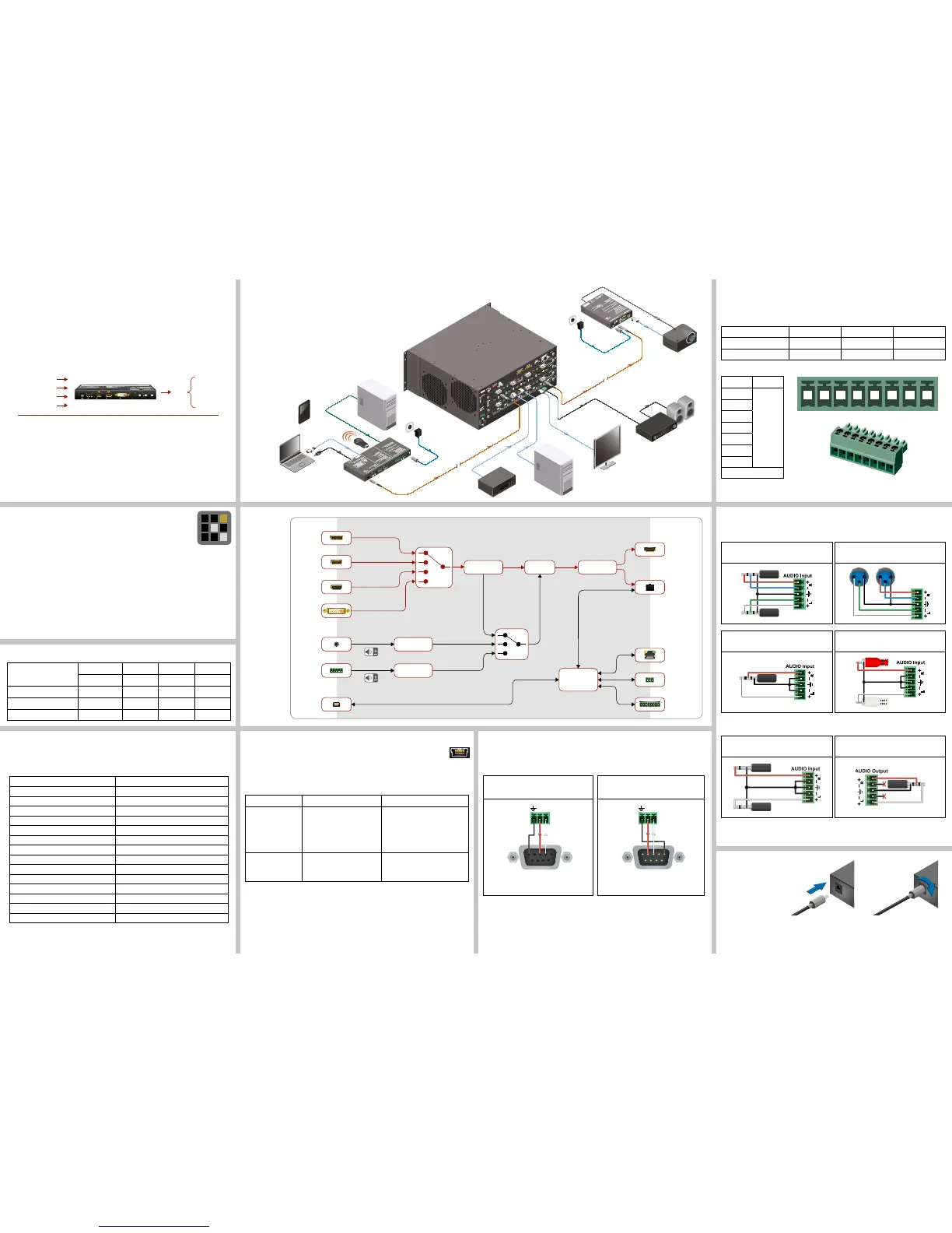
From balanced output to balanced input
2x6.3 (1/4”) TS - Phoenix
From balanced output to unbalanced input
Phoenix - 3.5 (1/8”) TRS
For more information about audio cable wiring see the user’s manual of the device or the
Wiring Guide on our website www.lightware.com.
1 2 3 4 5 6 7 8
GPIO - General Purpose Input/Output Ports
The device has seven GPIO pins which operate at TTL digital signal levels and can be set to
high or low level (Push-Pull). The direction of the pins can be input or output (adjustable). The
signal levels are the following:
Input voltage (V) Output voltage (V) Max. current (mA)
Logical low level 0 - 0.8 0 - 0.5 30
Logical high level 2 -5 4.5 - 5 18
GPIO connector and plug pin assignment
Pin nr. Signal
1
Congurable
2
3
4
5
6
7
Ground
The total available current of the controller is 180 mA.
Software Control – Using Lightware Device Controller (LDC)
The device can be controlled from a computer through the Ethernet port
using Lightware Device Controller. Please download the application from
www.lightware.com, install on a Windows PC or a macOS and connect to the
device via the Ethernet port.
The IP address of the unit is static (default): 192.168.0.100., DHCP is disabled.
Set Dynamic IP Address
1. Keep the Show Me button pressed for 5 seconds; all front panel LEDs start to blink.
2. Release the button, then press it 3 times quickly. DHCP is now enabled.
Fiber Optical Output Settings
ON: high-speed (AV signal) and low-speed (serial, USB) communication are transmitted.
STANDBY: only low-speed (serial, USB) communication is transmitted.
Restore Factory Default Settings
1. Keep the Show Me button pressed for 10 seconds; after 5 seconds front panel LEDs
start to blink but keep the buttons pressed; the LEDs start to blink faster 5 seconds later.
2. Release the button, then press it 3 times quickly; factory default settings are restored:
IP address (static) 192.168.0.100
Subnet mask 255.255.255.0
Static gateway 192.168.0.1
DHCP Disabled
TCP/IP port nr. LW2 / LW3 10001 / 6107
Crosspoint setting (Video/Audio) DisplayPort input
Autoselect (Video/Audio) Disabled
SC laser output Enabled
Emulated EDID Dynamic
RS-232 mode Pass-through
RS-232 control protocol LW2
RS-232 port setting 57600 BAUD, 8, N, 1
Command injection port (local / link) 8001 / 8002
GPIO output level High
GPIO direction Input
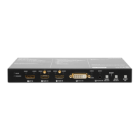
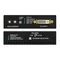
Port Diagram
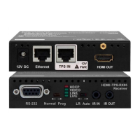
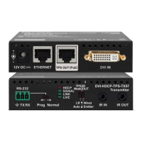
Typical Application
Integrated system diagram
Maximum Fiber Cable Extension Distances
OM1 OM2 OM3 OM4
(62.5/125) (50/125) (50/125) (50/125)
1080p@60Hz 24 bpp 250 m 600 m 1200 m 2500 m
1080p@60Hz 36 bpp 150 m 400 m 800 m 1300 m
4096x2048@30Hz 24 bpp Not supported 350 m 700 m 1100 m
Optical Extender Concept
SW4-OPT-TX240RAK has a multi-mode single ber output interface which is able to transmit
different type of signals at the same time. The device accepts digital video (DP, HDMI, and
DVI-D) and analog audio sources (Jack and 5-pole Phoenix). The unit can be controlled over
LAN, RS-232 (3-pole Phoenix), and USB interfaces, and is able to control third-party devices
using the built-in GPIO ports. Besides of these the transmitter also has USB KVM function.
One audio signal (original embedded or analog) and one video signal can be transmitted
via the optical output at the same time.
Compatible Devices
The transmitter is compatible with the following receivers and input boards:
HDMI-3D-OPT-RX150RA receiver;
MX modular frames with MX-DVI-OPT-IB and MX-HDMI-OPT-IB cards.
USB KVM Function
SW4-OPT-TX240RAK transmitter supports HID-compliant (Human Interface
Device) devices to transmit USB signal between the source and sink devices.
The transmitter connects to the controlled device (e.g. PC) and the controlling devices (e.g.
computer mouse, keyboard, touch panel) are connected to the receiver. USB KVM function
can be used in two different modes: Transparent and Composite mode.
Transparent mode Composite mode
Device support Supports all HID-compliant
devices.
Supports the following HID-
compliant devices: computer
mouse, keyboard built with up to
107 keys with or without specic
multimedia keys.
Driver software Driver for all connected USB
devices has to be installed on
the controlled computer.
No driver is needed for the
connected devices.
Locking DC Plug
Twist 90° clockwise to lock.
 Loading...