LINEAR INTERIOR SYSTEMS INC.
T. 905-265-0055 F. 905-265-0035 info@linearinteriorsystems.com www.linearinteriorsystems.com
1 3/4”
(45 mm)
1 3/8”
(35 mm)
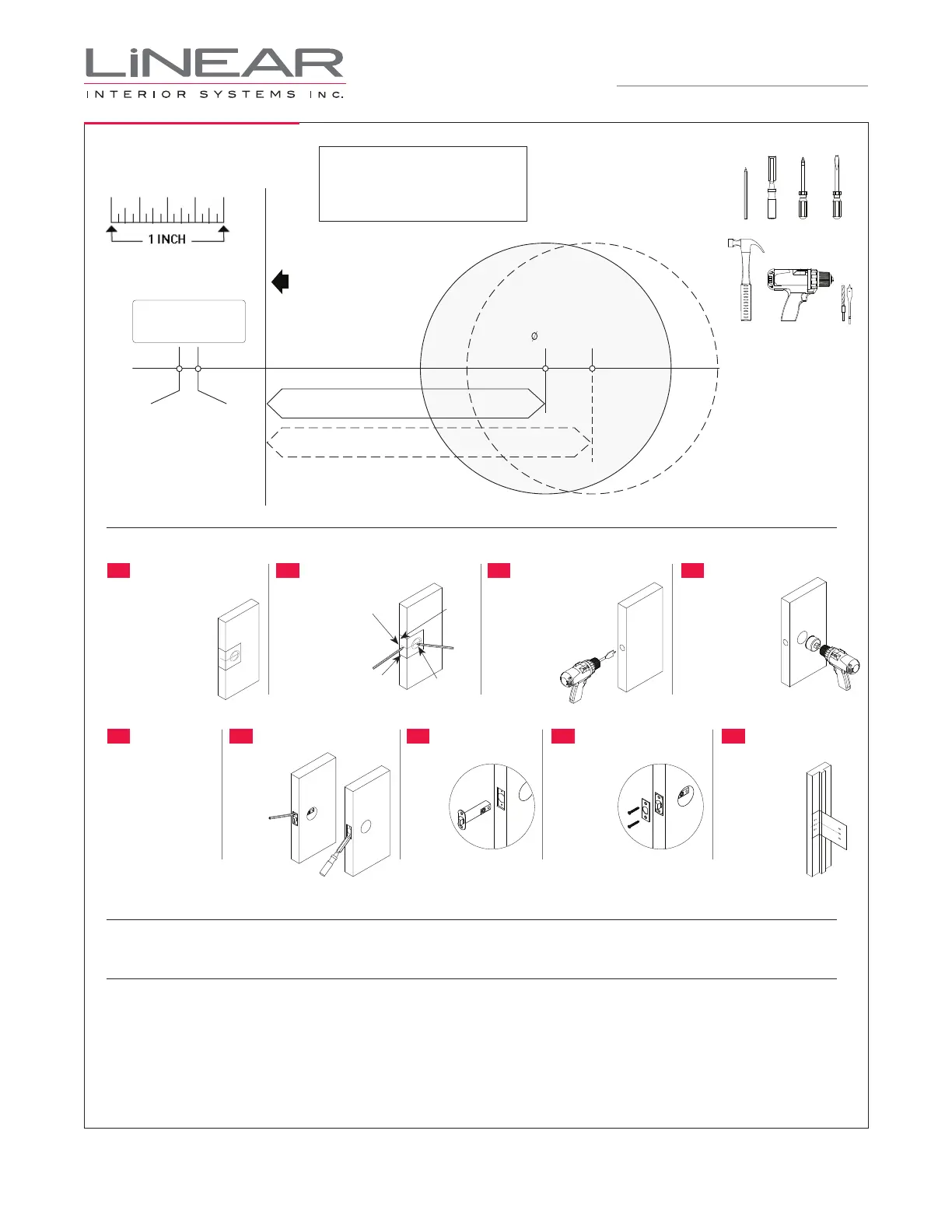
Drill a 1” (25mm) diameter
hole at the centre of
the door edge
Fold here
Place on the door edge
Backset - 2 3/8” (60 mm)
2 1/8” (54 mm)
Backset - 2 3/4” (70 mm)
PAGE 2
DOOR PREPARATION
TEMPLATE
NEW DOOR PREPARATION
HANDLE CARE
LIFETIME MECHANICAL AND FINISH WARRANTY
IMPORTANT: Print template
to scale if not factory supplied
instructions.
Wash and clean only with water and polish with a soft clean non abrasive cloth.
The product is warranted to be free from fi nish, mechanical and workmanship defects for the life of the product. Linear
Interior Systems Inc. will replace any Linear T300 Series Lockset which fails to meet this warranty. Any fi nish deterioration
from use of paints, solvents or chemicals is not a defect and therefore not covered by this warranty.
Linear will not be liable for any incidental damages. In the event that your Linear Lock does not meet the warranted quality,
return the product with proof of purchase to the dealer you purchased it from.
USE TEMPLATE PROVIDED
TO MARK CENTER HOLES
ON THE DOOR
POSITION
FACEPLATE
MARK DOOR
CHISEL MORTISE
DRILL EDGE BORE
INSERT LATCH
DRILL FACE BORE
ATTACH FACEPLATE INSTALL STRIKE
SEE PAGE 1 FOR LOCK
INSTALLATION INSTRUCTIONS
1
5
2
6
3
7
4
89
T300 Series
INSTALLATION INSTRUCTIONS
TOOLS NEEDED
PENCIL CHISEL PHILLIPS
SCREWDRIVER
FLAT HEAD
SCREWDRIVER
HAMMER DRILL BITS
Determine latch backset
(2 3/8” or 2 3/4”). Fold
enclosed template on
dotted line and locate on
door at desired height.
If door is bevelled, place
folded edge on low side
of bevel.
Position fi nished
faceplate over latch.
Slide latch into edge
bore. Check that
screw mounting points
are Centered before
tracing the outline of
the fi nished faceplate.
Mark door at
points 1, 2, 3
and 4 and centre
punch for drilling.
Remove latch.
Drill 1/8” screw
holes. Chisel
out mortise
5/32” deep.
Drill 1” dia. hole.
2 3/8” backset... drill 3 5/8” deep
2 3/4” backset... drill 4” deep
2 1/8” dia. drill bit.
Keep drill perpendicular
to door surface and drill
through.
Note: for wood doors: to
avoid splintering, drill a
centering hole through
the door, then drill face
bore from both sides.
Rotate head so
angled side is
toward strike
when door
closes. Position
fi nished
faceplate and
fasten with two
screws.
Using strike
template, mark
jamb, drill screw
holes and chisel
mortise at proper
location. Install
strike.
IMPORTANT
Before installing Strike,
please mount hardware
as shown in drawing.
Point 1
(edge bore)
Point 2
(face bore)
Point 3
(screw
mounting
points)
Point 4
(screw mounting
points)
With “UP”
side up,
slide latch
into edge
bore.
 Loading...