2. SETTING
THE
MAXIMUM
LIFT
ARMS
TRAVEL
The
condition
of
upper
lift
arms
stopping
at max·
imum
height should
occur
automatically
follow·
ing the rotation
of
the spool
to
neutral setting,
which allows the
inlet
oil
to
drain
out
freely.
If not, the piston would end
its
stroke when the
inside
rockshaft
control
lever is stopped by
the
hydraulic
lift
body and, under these
conditions,
the
oil
under pressure delivered by
the
pump
would drain
out
through
the
pressure relief valve.
Adjust
as follows:
1.
Apply a load
of
at least 110 lb.
(50
kg.)
to
the
three-point
lower
links.
2.
Start the engine. and run
it
up
to
medium
speed.
3.
Raise the arms and set the hydraulic
lift
con-
trol lever (Item
A,
Fig. C.0/20) at the highest
point in the control quadrant.
4.
In
this
position, scribe
two
assembly marks
(Items
s,
and
S2,
Diagram
C),
in register, on
the hydraulic
lift
body and on the cam in-
tegral with the right side arm.
5.
Slowly unscrew a few turns
the
arms max-
imum
lift
stop
screw (Item
10)
until
the
pressure relief valve (Item
1,
Fig. C.0/1)
opens.
6.
Make sure that the residual upward travel by
the
lift
arms
following
the opening
of
the
pressure relief valve is comprised between
0.158-0.197 in.
(4-5
mm.) in (Item d., Fig.
C.0/20) as measured at the quoted assembly
marks. If the residual travel
is
less, then
reduce the
shims
(Item
N)
under the head
of
the screw (Item 10), and
if
more, then add
shims.
In the course
of
adjustment,
hold
the
hydraulic
lift
control
lever at
the
lower
stop.
A CAUTION: No variation
of
the
lift
arms travel
length
following
a reduction
or
an Increase
of
the
number
of
shims
inserted under
the
head
of
the
screw
is probably caused by wrong assemblage
or
inside leverage deformation: In
this
case In-
spect and
check
the
hydraulic
lift
inside
com·
ponents.
3.
SENSITIVITY ADJUSTMENT
To be
functionally
efficient,
the
pulling
action
re-
quires
the
maximum
sensitivity
of
the reaction
by the control valve spool (Item 6, Fig. C.0/21).
55378
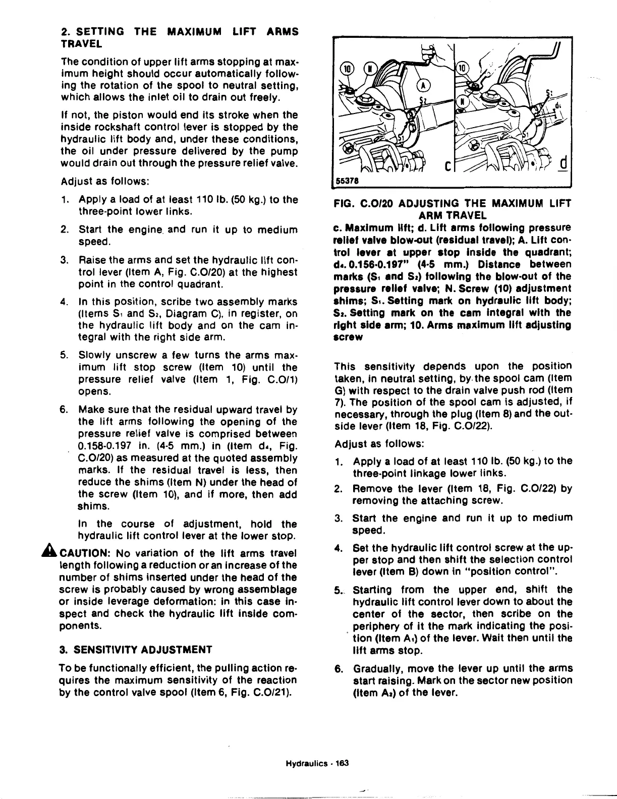
FIG. C.0/20 ADJUSTING THE MAXIMUM LIFT
ARM TRAVEL
c.
Maximum
lift;
d.
Lift
arms
following
pressure
relief valve blow-out (residual travel);
A.
Lift
con-
trol
lever
at
upper
stop
Inside the quadrant;
d •. 0.156·0.197" (4·5 mm.) Distance between
marks
(St
and
Sz)
following
the blow-out
of
the
pressure
relief
valve; N. Screw (10) adjustment
shims;
St.
Setting
mark
on
hydraultc
lift
body;
Sz.
Setting
mark
on
the
cam
Integral
with
the
right
side arm; 10.
Arms
maximum
lift
adjusting
screw
This
sensitivity
depends upon the
position
taken, in neutral setting,
by.
the spool cam (Item
G)
with
respect
to
the
drain valve push rod (Item
7).
The
position
of
the spool cam is adjusted,
if
necessary, through the plug (Item
8)
and the out-
side lever (Item
18,
Fig. C.0/22).
Adjust
as
follows:
1.
Apply a load
of
at least 110 lb.
(50
kg.)
to
the
three-point linkage lower links.
2.
Remove
the
lever (Item 18, Fig. C.0/22) by
removing
the
attaching
screw.
3.
Start
the
engine and run
it
up to medium
speed.
4.
Set
the
hydraulic
lift
control
screw at
the
up-
per
stop
and then
shift
the selection
control
lever (Item
B)
down
In
"position
control".
5. Starting
from
the
upper end,
shift
the
hydraulic
lift
control
lever
down
to
about the
center
of
the
sector, then scribe on
the
periphery
of
It
the
mark
indicating
the posi-
.
tlon
(Item At)
of
the lever. Wait then
until
the
lift
arms stop.
6. Gradually, move
the
lever up
until
the
arms
start raising. Mark on
the
sector
new position
(Item
Az)
of
the
lever.
Hydraulics - 163

 Loading...
