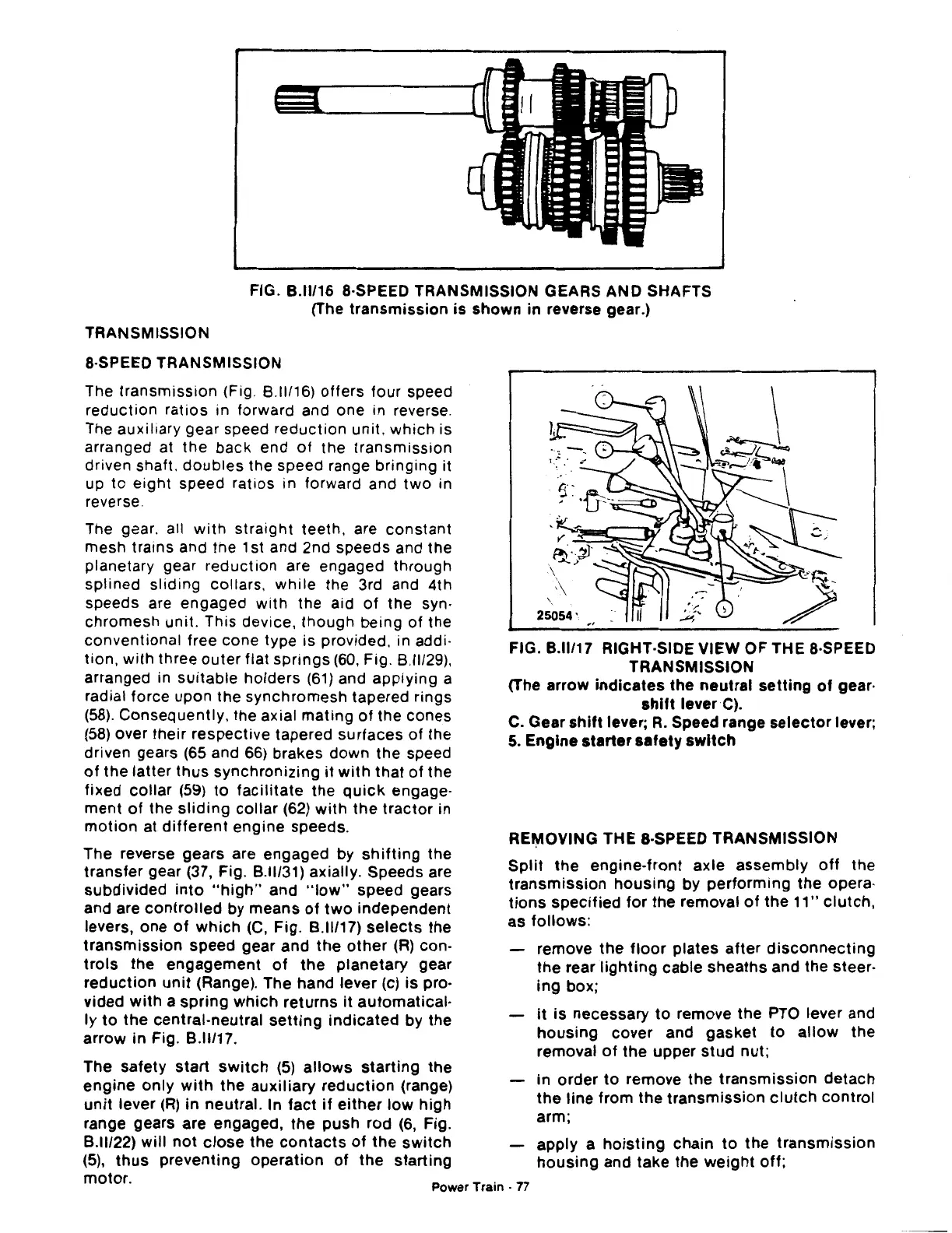
FIG.
8.11/16
8-SPEED TRANSMISSION GEARS AND SHAFTS
(The
transmission
is
shown
in
reverse gear.)
TRANSMISSION
8-SPEED TRANSMISSION
The
transmission
(Fig.
8.11116)
offers four speed
reduction ratios in forward and one in reverse.
The auxiliary gear speed reduction unit,
which
is
arranged at the back end
of
the
transmission
driven shaft.
doubles
the speed range bringing it
up
to
eight speed ratios in forward and
two
in
reverse.
The gaar. all
with
straight teeth, are constant
mesh trains and the 1st and 2nd speeds and the
planetary gear reduction are engaged through
splined sliding collars.
while
the 3rd and 4th
speeds are engaged
with
the aid
of
the syn·
chromesh unit. This device,
though
being of the
conventional free cone type is provided. in addi-
tion,
with
three
outer
flat
springs
(60,
Fig.
8.11129),
arranged in suitable holders
(61)
and applying a
radial force upon the synchromesh tapered rings
(58).
Consequently, the axial mating
of
the cones
(58)
over their respective tapered surfaces of the
driven gears
(65
and
66)
brakes down the speed
of
the latter
thus
synchronizing
it
with
that of the
fixed collar
(59)
to
facilitate
the
quick
engage-
ment
of
the
sliding
collar
(62)
with
the
tractor
in
motion
at
different
engine speeds.
The reverse gears are engaged by
shifting
the
transfer
gear (37, Fig.
8.11131)
axially. Speeds are
subdivided
into
"high"
and
"low"
speed gears
and are
controlled
by means
of
two
independent
levers, one
of
which
(C,
Fig.
8.11117)
selects
the
transmission
speed gear and the
other
(R)
con-
trols
the engagement
of
the
planetary gear
reduction
unit
(Range). The hand lever (c)
is
pro·
vided
with
a spring
which
returns
it
automatical·
ly
to
the
central-neutral
setting
indicated
by the
arrow in Fig.
8.11/17.
The safety
start
switch
(5)
allows
starting
the
engine
only
with
the auxiliary
reduction
(range)
unit
lever
(R)
in neutral. In
fact
if
either
low
high
range gears are engaged,
the
push rod
(6,
Fig.
8.11122)
will
not
close
the
contacts
of
the
switch
(5),
thus
preventing operation
of
the
starting
FIG.
8.11/17
RIGHT-SIDE VIEW OF THE 8·SPEED
TRANSMISSION
(The arrow
indicates
the neutral
setting
of
gear·
shift
lever
C).
C. Gear
shift
lever;
R.
Speed range
selector
lever;
5.
Engine
starter
safety
switch
RE~OVING
THE 8-SPEED TRANSMISSION
Split
the engine-front axle assembly
off
the
transmission
housing
by
performing
the
opera-
tions
specified
for
the removal
of
the
11"
clutch,
as
follows:
remove the
floor
plates
after
disconnecting
the
rear
lighting
cable sheaths and the steer-
ing
box;
it
is
necessary
to
remove the
PTO
lever and
housing
cover and gasket
to
allow
the
removal
of
the upper
stud
nut;
in
order
to
remove the
transmission
detach
the line from
the
transmission
clutch
control
arm;
apply a
hoisting
chain
to
the
transmission
housing
and take the
weight
off;
motor.
Power Train -
77

 Loading...
