I235PLGB0708_PMA50 Str. 1/5
PL
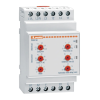
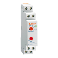
Przekaźnik ochrony pompy Pump protection relay
przed niedociążeniem for motor under-load and
i przetężeniem over-current monitoring
PMA50
A1 A2 Y
L1/L L2/N L3
Underload
0.99
0.1
Overcurrent
I MAX [% Ie]
Mode
A
H
C
B
D
F
G
E
80
100
40
10
20
Cosfi MIN
60
Lovato
0.2
PMA 50
0.8
0.4
0.6
B1 C
1412 11
10
0.1
Automatic reset delay [min]
Inhibition time [s]
OFF
25
100
75
50
Trip delay [s]
20
1
40
60
4
2
8
6
Schemat podłączenia przekładnika
w układzie trójfazowym
Wiring diagram for three-phase connection
by CT
600V16A
METER
A1
A2
Y
14
12
11
B1
L2
L3
L1
L1/L
C
L2/N
L3
O
A
D
L
Schemat podłączenia bezpośredniego
w układzie trójfazowym
Wiring diagram for three-phase direct
connection
600V16A
METER
A1
A2
Y
14
12
11
B1
L2
L3
L1
L1/L
C
L2/N
L3
O
A
D
L
UWAGA! By uniknąć uszkodzeń i zagrożenia życia
urządzenia te powinny być instalowane przez
wykwalifikowany personel oraz w zgodzie
z odpowiednimi przepisami.
● Produkty zaprezentowane w poniższym dokumencie mogą zostać
zmienione lub ulepszone bez konieczności wcześniejszego
informowania o tym.
● Dane techniczne oraz opisy oddają w jak najdokładniejszy sposób
posiadaną przez nas wiedzę, jednak nie bierzemy odpowiedzialności
za ewentualne błędy, braki oraz sytuacje awaryjne.
● W układzie należy zamontować rozłącznik, który musi znajdować
się niedaleko urządzenia i być łatwo dostępny
dla operatora. Musi spełniać wymogi następujących norm: IEC/ EN
61010-1 § 6.12.2.1.
● Należy zainstalować urządzenie w obudowie lub szafie
o minimalnym stopniu ochrony IP40.
Opis
Przekaźnik PMA50 jest urządzeniem, które zapewnia 4 typy
ochrony silnika: kolejność faz, zanik fazy, przetężenie silnika
i zbyt małe obciążenie silnika, poprzez kontrolę Cosφ.
Przekaźnik znajduje swoje zastosowanie w aplikacjach
ochrony pomp, dzięki funkcjom kontroli, przed suchobiegiem.
Może być również stosowany do wykrywania przerwy
w mechanizmach transmisji, takich jak pasy transmisyjne,
taśmy i do ochrony przed blokadą systemu transmisyjnego.
Urządzenie posiada automatyczne kasowanie po wykryciu
niedociążenia. Ta funkcja pozwala na ponowne uruchomienie
pompy w celu uzupełnienia poziomu płynu.
Charakterystyka
- Kontrola niedociążenia (suchobieg) przez pomiar Cosφ
- Kontrola TRMS prądu maksymalnego
- Zasilanie pomocnicze odseparowane od napięcia
kontrolowanego
- Kontrola kolejności faz i zaniku fazy
- Podłączenie bezpośrednie lub przez przekładnik prądowy
- Wejście uruchomienia/kasowania
- Wejście prądowe: 16A
- Wybór pomiędzy 2 zakresami skali prą
dowej: 5A lub 16A
- Regulacja progu min Cosφ: 0,1...0,99
- Regulacja progu prądu max: 10...100%
- Czas blokady: 1...60 sek
- Opóźnienie zadziałania: 0,1...10 sek
- Opóźnienie automatycznego kasowania:
OFF...100 min
- Stała histereza 0,03 dla Cosφ i 3% dla przeciążenia.
- 1 wyjście przekaźnikowe z zestykiem przełącznym
- Zielony wskaźnik LED dla włączonego zasilania
i stanu blokady
- Czerwony wskaźnik LED dla sygnalizacji zadziałania przy
minimum Cosφ
- Czerwony wskaźnik LED dla sygnalizacji zadziałania przy
maksimum prądu.
Wybór trybu pracy
UWAGA
Zaleca się dokonywanie zmiany trybu pracy przy wyłączonym
urządzeniu, by uniknąć niebezpiecznych sytuacji podczas
zmiany funkcji. Niemniej, możliwa jest zmiana przy zasilonym
urządzeniu. Regulacja przełącznikiem powoduje jednoczesne
mruganie wszystkich wskaźników LED przez 5 sekund,
następnie urządzenie dokonuje kasowania i włącza się
z nowym trybem pracy.
Odpowiednia regulacja pokrętłem [5] pozwala na wybór
wymaganego trybu pracy:
Tryb Ie
Podłączenie
Kasowanie
A 5A
1F
OFF
B 5A
1F
ON
WARNING! This equipment is to be installed by qualified
personnel, complying to current standards, to avoid
damages or safety hazards. Products illustrated herein
are subject to alteration and changes without prior notice.
● Technical data and descriptions in the publication are accurate, to
the best of our knowledge, but no liabilities for errors, omissions or
contingencies arising therefrom are accepted.
● A circuit breaker must be included in the electrical installation of the
building. It must be installed close by the equipment and within easy
reach of the operator.
It must be marked as the disconnecting device of the equipment:
IEC /EN 61010-1 § 6.12.2.1
● Fit the instrument in an enclosure or cabinet with minimum IP40
degree protection.
Description
The PMA50 relay is a device which includes 4 motor
protections: phase sequence, phase loss, over-current and
too low motor load by controlling the cosφ value.
The relay finds its ideal application in the protection of pumps
since it conducts control functions to exclude dry pump
running and to stop it. It can be also used o detect the
breakage of transmission mechanisms, such as belts, joints,
and to protect against the blockage of a transmission system.
It has an automatic reset time for under-load tripping. This
function provides for the pump restarting once the well level is
restored.
Characteristics
- Under-load control (dry running) by cosφ measurement
- TRMS maximum current control
- Power supply voltage separated from control voltage
- Sequence and phase failure control
- Connection either directly or by external CT
- Consent input for running/resetting
- Current input: 16A
- Choice of 2 different current scales: 5A or 16A
- Min cosφ threshold adjustment: 0.1...0.99
- Max current threshold adjustment: 10...100%
- Inhibition time: 1...60 seconds
- Tripping delay: 0.1...10 seconds
- Delayed automatic resetting:
OFF...100 minutes
- Fixed hysteresis: 0.03Cosφ and 3% for overload
- 1 relay output with changeover contact
- Green LED indicator for power on and inhibition state
- Red LED indicator for minimum cosφ tripping
- Red LED indicator for maximum current tripping.
Operating mode Choice
ATTENTION
It is recommended to make the operating mode choice when
the device is switched off to avoid dangerous conditions
during function change. It is however possible to make the
change with a powered device. The selector adjustment
causes the simultaneous flashing of all the LEDs for 5
seconds, the device reset and subsequent power up with the
new operating mode.
Regulate the relative rotary switch [5] to the required
operating mode:
Mode
Ie Wiring
Ext.
reset
5A 1Ph OFF
B
5A 1Ph ON
1
2
3 4
5
6