Four Mounting Holes
Diameter - 0.25 in. (6mm)
Four Screws
Secure Cover
6.10 in.
(155 mm)
3.30 in.
(84 mm)
12.50 in.
(318 mm)
Wall
11.75 in.
(298 mm)
4.0 in.
(102 mm)
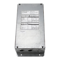
COOPERSBURG, PA 18036 U.S.A.
G 2 CB
144-317 Rev. 1.9
0-10V INTERFACE CONTROL
Control Input:
100-120V
, 220-240V 50/60Hz
Switched Output: 100-277
GRX-TVI
Incandescent
16A
Fluorescent
5A
Magnetic Low-voltage
16A
Electronic Low-voltage 16A
Neon/Cold Cathode 16A
Motor
1/4 HP@120V
1/2 HP@277V
®
Control
GRX-TVI Input Rating
I
H
2
0.02A
I
DH
2
0.1A
Load T
ype Switched
Ratings
®
10A
5AX
10A
10A
10A
Control
GRX-TVI Input Rating
I
H
2
0.02A
I
DH
2
0.1A
Load Type Switched
Ratings
✔
ACN
003 715 277
0-10V Output Rating
Max. 0.3A PELV
0-10V Output Rating
Max.
0.3A Class 2
Switched µ
Installation and Operation Instructions
Read Befor
e Installing
Occupant Copy
GRX-TVI Control Interface
Phase Control to 0-10V
Description
The GRX-TVI provides 0-10V control and ballast switching capabili-
ties in one enclosure. The GRX-TVI gives
GRAFIK Eye 3000 Series
Control Units the ability to control any 0-10V ballasts powered by
100V-277V (
ballast must provide 0-10V sourcing of current)
and provides switching relays that can handle the in-rush current for a
circuit of ballasts. The GRX-TVI gives a
GRAFIK Eye 3000 Series
Control Unit the ability to both dim and switch electronic ballasts,
such as
Lutron's Eco-10
™
(TVE models). The GRX-TVI can also be
used to switch any of the load types listed below.
Note: When using a Control Unit, a GRX-TVI is required for each 0-10V
fluorescent zone. (A 3-zone Control Unit with two fluorescent zones
and one incandescent zone is shown as an example.)
Mounting
Find a suitable location for mounting.
n Decide on the pr
oper location for the GRX-TVI (NEMA Type 1
enclosur
e, indoor use only). See System Wiring Layout below.
n The envir
onment where the GRX-TVI is placed must have an
ambient temperature range of 32—104 °F (0—40 °C).
n Mount the enclosur
e vertically on a wall (screws not provided). See
Mounting Diagram below.
n Mounting method must be able to support weight and forces
applied during installation.
n Iinternal relays will click while in operation — mount where
audible noise is acceptable.
System Wiring Layout
Mounting Diagram
Product Specifications
Four Mounting Holes
Diameter: 0.25 in. (6 mm)
Four Screws Secure Cover
12.5 in.
(318 mm)
3.30 in.
(84
mm
)
6.10 in.
(155
mm
)
0-10V C
ontrol Fluorescent Zone/Load 1
0-10V C
ontrol Fluorescent Zone/Load 1
0-10V Ballast
Power from
Distribution
Panel
GRX-
TVI
GRX-
TVI
B
allast
Switched Fluorescent
Zone/Load 2
Incandescent Zone/Load 3
Control Unit
C
lass 2/PELV Accessory Controls
0-10V B
allast
COOPERSBURG,
PA 18036 U.S.A.
G 2 CB
144-317 Rev. 1.9
0-10V INTERFACE CONTROL
Control Input:
100-120V, 220-240V 50/60Hz
Switched Output: 100-277
GRX-TVI
Incandescent 16A
Fluorescent 5A
Magnetic Low-voltage 16A
Electronic Low-voltage 16A
Neon/Cold Cathode 16A
Motor 1/4 HP@120V
1/2 HP@277V
®
Control
GRX-TVI Input Rating
I
H
2
0.02A
I
DH
2
0.1A
Load Type Switched
Ratings
®
10A
5AX
10A
10A
10A
Control
GRX-TVI Input Rating
I
H
2
0.02A
I
DH
2
0.1A
Load Type Switched
Ratings
✔
ACN
003 715 277
0-10V Output Rating
Max. 0.3A PELV
0-10V Output Rating
Max. 0.3A Class 2
Switched µ
4.0 in.
(102 mm)
11.75 in.
(298
mm)
W
ALL
100-127V/
200-277V
230V
(
CE
)
FEATURES
.....................Provides a Class 2/PELV isolated 0-10V output signal that
conforms to EN60929 and IEC60929
Accepts a constant-gate drive fluorescent signal (100-127V,
220-240V, 50/60Hz)
INPUT POWER RA
TING
................
100-127/220-240V, 50/60Hz
H2/L2 TERMINAL.........................20mA
INPUT RA
TING
DH2/DL2 TERMINAL
.....................100mA
INPUT RATING
0-10V OUTPUT RATING
...............10µA-300mA - Sinks current only (maximum 150
ballasts)
Source/Load Type
Fluorescent:
Lutr
on
Eco-10
T
(TVE Series)
Electronic Capacitive
Non-Dim
Other Manufactur
er
’
s 0-10V
Ballasts
(0-10V source only)
Incandescent
Low-Voltage
Metal Halide
Neon/Cold Cathode
16A
16A
16A
16A
16A
16A
16A
—
10A
10A
10A
10A
10A
10A
Motors 1/4HP @ 100-120V
1/2HP @ 200-277V
1/2HP @ 230V CE
TERMINALS Two #12-20AWG (0.5-2.5 mm
2
) conductors per terminal.
MOUNTING NEMA Type 1 enclosure, indoor use only.
ENVIRONMENTAL 32—104 ˚F (0—40 ˚C).
WEIGHT 4.25 lb. (2kg)
100-127V and 220-240V/CE
Chinese
English
Español
Français
Por
tuguês
Nederlands
Deutsch
Chinese
Italiano