Solid-Ceiling Mounting
• Drill two 3/16 in (4.6 mm) pilot holes for the provided
screw anchors.
• Press the anchors into the holes and tap flush with a
hammer.
• Place the flat side of the mounting bracket against the ceiling
and install the two provided screws using a hand screwdriver.
• Attach the Sensor to the mounting bracket by inserting and
twisting in a clockwise direction until the Sensor locks into
place.
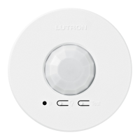
With the Sensor mounted on the ceiling, press and release the “Test” button. The
lens will glow briefly, indicating the test mode has been entered.
NOTE: There is a warm-up period of 90 seconds after the battery is installed
before the test mode is activated. If the button is pressed during this time, the
lens will flash continuously until the warm-up period is complete, and then the test
mode will be automatically entered.
Confirm the coverage area by walking through the space and observing the lens. The lens will glow solid every
time motion is detected. If the lens remains off during motion, the Sensor cannot detect motion at that location.
Press and release the “Test” button again to exit the test mode. If the button is not pressed, the test mode will
automatically time out 15 minutes after being enabled, or 5 minutes after the last detected motion if the room
is vacated.
If the Sensor has significant trouble detecting motion during the test, it should be moved to another
location and re-tested. NOTE: If the Sensor is detecting motion in areas that are not desirable, such as
hallways or adjacent rooms, refer to www.lutron.com/occsensors
If Sensor detection is satisfactory during this test, perform the wireless communication test as described in
section G. Testing Wireless Communication.
This test should be performed to verify the Sensor has been correctly set up with
the corresponding dimming or switching device and that there is proper wireless
communication from the chosen Sensor location.
Press and release the “Light” button multiple times to toggle the lights on and off.
English
Radio Powr Savr
™
Installation Instructions
Please Read Before Installing
Wireless Battery-Powered Occupancy and
Vacancy Sensors California Title 24 Compliant
LRF2-OCR2B-P 3 V- 14 mA 434 MHz (Occupancy / Vacancy)
LRF2-VCR2B-P 3 V- 14 mA 434 MHz (Vacancy Only)
Compatible Products/Additional Information
For a full list of compatible products and other additional information visit www.lutron.com/occsensors
Product Description
Lutron’s ceiling-mounted Occupancy and Vacancy Sensors are wireless, battery-powered, passive infrared (PIR)
devices that automatically control lights via RF communication with a dimming or switching device.
Important Notes
1. This Sensor is part of a system and cannot be used to control a load without a compatible dimming or
switching device. Refer to the instruction sheets of the receiving device(s) for installation information.
2. Use only high-quality lithium batteries, size CR123, 3 V- (ANSI-5018LC, IEC-CR17345). DO NOT
use rechargeable batteries. Using improperly rated batteries could damage the Sensor.
NOTICE: DO NOT disassemble, crush, puncture, or incinerate batteries. DO NOT dispose of batteries in
normal household waste. Please recycle, take to a proper battery disposal facility, or contact your local waste
disposal provider regarding local restrictions on the disposal or recycling of batteries.
WARNING: Entrapment hazard. To avoid the risk of entrapment, serious injury, or death, these
controls must not be used to control equipment which is not visible from every control location or
which could create hazardous situations such as entrapment if operated accidentally. Examples
of such equipment which must not be operated by these controls include (but are not limited to)
motorized gates, garage doors, industrial doors, microwave ovens, heating pads, etc. It is the
installer’s responsibility to ensure that the equipment being controlled is visible from every control
location and that only suitable equipment is connected to these controls. Failure to do so could result
in serious injury or death.
FCC/ IC Information
This device complies with part 15 of the FCC Rules and Industry Canada license-exempt RSS standard(s).
Operation is subject to the following two conditions: (1) This device may not cause interference, and (2) this device
must accept any interference, including interference that may cause undesired operation. Modifications not
expressly approved by Lutron Electronics Co., Inc. could void the user’s authority to operate this equipment.
Note: This equipment has been tested and found to comply with the limits for a Class B digital device, pursuant
to part 15 of the FCC Rules. These limits are designed to provide reasonable protection against harmful
interference in a residential installation. This equipment generates, uses and can radiate radio frequency energy
and, if not installed and used in accordance with the instructions, may cause harmful interference to radio
communications. However, there is no guarantee that interference will not occur in a particular installation. If
this equipment does cause harmful interference to radio or television reception, which can be determined by
turning the equipment off and on, the user is encouraged to try to correct the interference by one or more of
the following measures:
—Reorient or relocate the receiving antenna.
—Increase the separation between the equipment and receiver.
— Connect the equipment into an outlet on a circuit different from that to which the receiver is connected.
—Consult the dealer or an experienced radio/TV technician for help.
Sensor Operation
Occupancy Version – The Sensor will automatically turn the lights on when the space is occupied and
automatically turn the lights off after the space is vacated.
Vacancy Only Version – The lights must be manually turned on at the dimming or switching device. The Sensor
will automatically turn the lights off after the space is vacated.
Limited Warranty
(Valid only in U.S.A., Canada, Puerto Rico, and the Caribbean.)
Lutron will, at its option, repair or replace any unit that is defective in materials or manufacture within one year after purchase. For
warranty service, return unit to place of purchase or mail to Lutron at 7200 Suter Rd., Coopersburg, PA 18036-1299, postage pre-paid.
This warranTy is in lieu of all oTher express warranTies, and The implied warranTy of merchanTabiliTy
is limiTed To one year from purchase. This warranTy does noT cover The cosT of insTallaTion, removal or
reinsTallaTion, or damage resulTing from misuse, abuse, or damage from improper wiring or insTallaTion.
This warranTy does noT cover incidenTal or consequenTial damages. luTron’s liabiliTy on any claim for
damages arising ouT of or in con nec Tion wiTh The manufacTure, sale, insTallaTion, delivery, or use of The
uniT shall never exceed The pur chase price of The uniT.
This warranty gives you specic legal rights, and you may have other rights which vary from state to state. Some states do not allow
the exclusion or limitation of incidental or consequential damages, or limitation on how long an implied warranty may last, so the
above limitations may not apply to you.
Technical Assistance
For questions concerning the installation or operation of this product, call the Lutron Technical Support Center.
Please provide exact model number when calling.
U.S.A. and Canada (24 hrs / 7 days) Brazil (Monday-Friday 8:30am - 5:30pm BRT)
1.800.523.9466 +55 (11) 3257-6745
Mexico 8am – 8pm ET
+1.888.235.2910 Fax +1.610.282.6311
Other countries 8am – 8pm ET
+1.610.282.3800 www.lutron.com
Instructions
1
2
1
Before setting up the Sensor, the corresponding dimming or switching device(s) must be installed.
Twist and remove mounting bracket to insert battery into battery cavity.
In order for the Sensor to operate properly, it must first be set up with a corresponding dimming or
switching device. The procedure for setting up a Sensor with a Maestro WirelessR (MRF2 only)
Dimmer or Electronic Switch is detailed below. If setting up a Sensor with a different device,
visit www.lutron.com/occsensors or consult the installation guide for that device.
Setting up a Sensor with a Maestro Wireless® Dimmer or
Electronic Switch
Place the Dimmer or Switch in set-up mode by pressing and
holding the tap button for 6 seconds until all LEDs on the device
begin flashing. Release the tap button.
Add the Sensor to the Dimmer or Switch by pressing and holding the
“Light” button on the front of the Sensor for 6 seconds until the lens
flashes briefly. The lights in the room will also flash 3 times, indicating
the Sensor has been successfully added. The Dimmer or Switch will exit
set-up mode automatically.
The “Light” button should now switch the lights in the room on and off when pressed. Repeat the above
procedure to set up the Sensor with additional devices.
2
1
1
4
5
3
2
A
Pre-Installation
B
Set-Up
G
Testing Wireless Communication
C
Sensor Detection Range
E
Mounting Methods
D
Sensor Placement and Coverage
F
Testing Sensor Coverage
Drop-Ceiling Mounting
Put the Sensor in place on the tile and either take the tile down or remove an
adjacent tile to gain access to the legs of the mounting wire on the back
of the tile. Twist the wire legs together tightly.
NOTE: For details on temporary
mounting on solid ceiling surfaces,
visit www.lutron.com/occsensors
Before mounting the Sensor, please note the following:
• The Sensor is designed for ceiling use only. DO NOT install on ceilings higher than 12 ft (3.7 m).
(See section C. Sensor Detection Range)
• The Sensor should be installed in a location where it has a good view of all parts of the room. The
Sensor requires line of sight to operate properly. If you cannot see the Sensor, it cannot see you.
The Sensor cannot see through glass objects such as patio or shower doors. (See section C. Sensor
Detection Range)
• DO NOT mount the Sensor within 6 ft (1.8 m) of HVAC vents or microwave ovens, within 6 in (15 cm)
of other RF devices, or within 4 ft (1.2 m) of light bulbs installed below the ceiling line. (See section
C. Sensor Detection Range)
• The Sensor may be installed up to 60 ft (18.3 m) away from the associated dimming or switching
device(s) if they are in direct line of sight. If there are walls or other barriers between the Sensor and
receiving device(s), the Sensor should be located within 30 ft (9.1 m). (See section C. Sensor Detection
Range)
• Whenever possible, avoid placing the Sensor in a location where it has a broad view outside the intended
space. If this is unavoidable, the lens can be masked to block the view of undesired areas
(see www.lutron.com/occsensors).
2
Lutron Electronics Co., Inc.
7200 Suter Road
Coopersburg, PA 18036-1299, U.S.A.
P/N 041416 Rev. B 07/2014
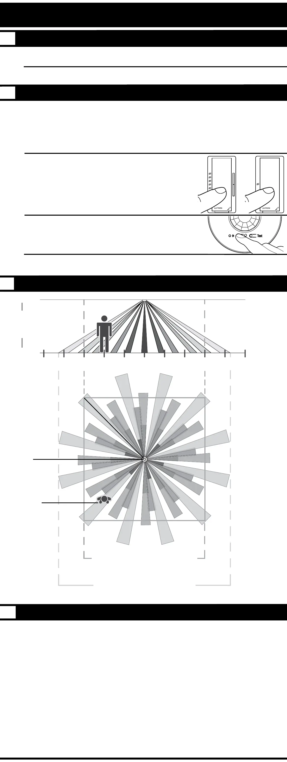
3
13 ft (4.0 m)
Radius of Coverage at Floor when
mounted on an 8 ft (2.4 m) Ceiling
15 ft 12 ft 9 ft 6 ft 3 ft 0 ft 3 ft 6 ft 9 ft 12 ft 15 ft
(4.6 m) (3.7 m) (2.7 m) (1.8 m) (0.9 m) (0 m) (0.9 m) (1.8 m) (2.7 m) (3.7 m) (4.6 m)
8 ft
(2.4 m)
Ceiling
height
Ceiling
Floor
Radius of Coverage at Floor
Sensor
Occupant
18 x 18 ft (5.5 x 5.5 m)
Maximum Room Dimensions
for Complete Coverage when
mounted on an 8 ft (2.4 m) Ceiling
Symptom Possible Causes Solution
Lights do not turn ON when space is
occupied.
Sensor is not correctly added to dimming / switching device(s). Refer to section B. Set-Up.
Sensor’s Auto-On setting is set to “Low light” or “Disabled”. Refer to section H. Advanced Set-Up.
The lights were recently turned off manually and the timeout has
not yet expired.
For more details, refer to Frequently Asked Questions at www.lutron.com/occsensors
Sensor does not have full view of room. Refer to section C. Sensor Detection Range.
Sensor is outside wireless range of dimming/switching device. Refer to section D. Sensor Placement and Coverage or G. Testing Wireless Communication.
Battery has been installed incorrectly. Refer to section A. Pre-Installation.
Dimming/switching device has been improperly wired. Refer to the instruction sheet of the receiving device or call Lutron Technical Support Center at 800.523.9466.
Light bulb(s) burned out.
Breaker is off or tripped.
Lights turn OFF while space is occupied. Sensor’s timeout is too short for this application. Refer to section H. Advanced Set-Up.
Sensor does not have full view of room. Refer to section C. Sensor Detection Range.
Lens mask is improperly applied. Refer to www.lutron.com/occsensors
Sensor’s activity setting is too low. Refer to section H. Advanced Set-Up.
Lights stay ON after space is vacated. Sensor’s timeout has not yet expired. Refer to section H. Advanced Set-Up.
An external noise source such as an HVAC vent is interfering. Try moving Sensor to a new location or reducing sensitivity. Refer to section D. Sensor Placement and
Coverage or H. Advanced Set-Up.
Battery has been installed incorrectly. Refer to section A. Pre-Installation.
Lights turn ON when walking past room. Sensor coverage extends beyond room perimeter. Refer to section D. Sensor Placement and Coverage.
Behavior of lights does not match Sensor
settings.
The intended setting was not saved. Refer to section H. Advanced Set-Up.
Multiple Sensors are added to a dimming/switching device and
their settings do not match.
Refer to section H. Advanced Set-Up.
Sensor lens does not glow in response to
motion during Sensor coverage testing.
Sensor cannot see motion due to obstruction. Move Sensor to another location. Refer to section C. Sensor Detection Range.
Room is too big or oddly shaped. Multiple Sensors may be necessary for full room coverage. For more details, refer to Frequently Asked
Questions at www.lutron.com/occsensors
Battery has been installed incorrectly. Refer to section A. Pre-Installation.
Lens does not stop glowing during Sensor
coverage testing even when there is no
motion.
An external noise source such as an HVAC vent is interfering. Try moving Sensor to a new location or reducing sensitivity. Refer to section D. Sensor Placement and
Coverage or H. Advanced Set-Up.
Lights do not respond correctly during
wireless communication testing.
Sensor is not correctly added to dimming / switching device. Refer to section B. Set-Up.
Sensor is outside wireless range of dimming/switching device. Move Sensor closer to dimming/switching device and retry test. Refer to section G. Testing Wireless
Communication.
Battery has been installed incorrectly. Refer to section A. Pre-Installation.
Dimming/switching device has been improperly wired. Refer to the instruction sheet of the receiving device or call Lutron Technical Support Center at 800.523.9466.
Light bulb(s) burned out.
Breaker is off or tripped.
Sensor lens flashes and lights do not turn
ON when space is occupied.
Battery is low. Replace battery. For more details, refer to Frequently Asked Questions at www.lutron.com/occsensors
Sensor is in test mode. Remove sensor from test mode. Refer to section F. Testing Sensor Coverage.
Troubleshooting
The Sensor features several advanced set-up modes. For the majority of installations, the default
settings will provide the best performance and you will not need to utilize the advanced set-up.
The Occupancy version of the Sensor has three adjustable advanced set-up modes:
Timeout, Auto-On, and Activity. The Vacancy-Only version has only two modes
(Auto-On not available). The default settings are listed below.
Default Settings:
Timeout: 15 minutes
Auto-On: Enabled
(Occupancy version only)
Activity: Low Activity
Advanced Set-Up Modes
Timeout
The Sensor will turn the lights off if no motion occurs for the duration of the timeout period. There are
four available timeout settings: 1*, 5, 15, and 30 minutes.
Auto-On (Occupancy version only)
The automatic-on functionality of the Sensor can be adjusted to control how the lights respond upon
initial occupancy. There are three available settings: Always, Low light, and Disable.
Enabled: The lights will always turn on.
Low light: The lights will only turn on automatically upon entry if there is not already sufficient
ambient light in the room.
Disabled: This setting converts the Sensor to vacancy mode. The lights will not automatically turn
on but will still automatically turn off after vacancy. The lights must be manually turned on by using the
associated dimming or switching device.
Activity
The sensitivity of the Sensor can be adjusted based on the expected level of activity within the room.
There are three available activity settings: Low Activity, Medium Activity, and High Activity.
Low Activity: This is the most sensitive setting and will detect very slight motions. This is the
recommended setting, as it will work well for nearly all applications. It is ideal for spaces where
occupants will often be seated for long periods of time.
Medium Activity**: This setting is slightly less sensitive than the Low Activity setting and can be
used for spaces that experience normal activity.
High Activity**: This is the least sensitive setting and can be used for spaces that will generally
only experience large motions, such as foot traffic.
* To select a 1-minute timeout, press and hold the timeout button for approximately 10 seconds until all
3 LEDs begin flashing rapidly. To save the 1-minute timeout setting, press and hold the timeout button
until all 3 LEDs turn on solid, indicating the 1-minute timeout has been saved.
** The Low Activity setting is the default and will perform best for most applications. Rarely, if the Sensor
is placed near external noise sources such as heating vents, air conditioning vents, or light bulbs, it
may turn the lights on without occupancy or keep the lights on too long after vacancy. If this occurs,
changing the sensitivity to Medium Activity or High Activity should resolve the problem.
 Loading...