Repair
P 2 / 5
< 1 > Lubrication
Apply 15 g of MAKITA grease K No.1 in gear housing
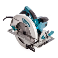
< 2 > Separating base from the motor section
( 1 ) After pulling base down to the minimum cutting depth, disassemble blade case cover by taking off 3 pcs. of
tapping screws CT 4x20 as illustrated in Fig.1 for easy disassembling in the next process.
First of all, detach the saw blade for safety repair.
Blade case cover
Fig.1
( 2 ) Disassemble tension spring 4, retaining ring S-40 and safety cover as illustrated in Fig. 1A.
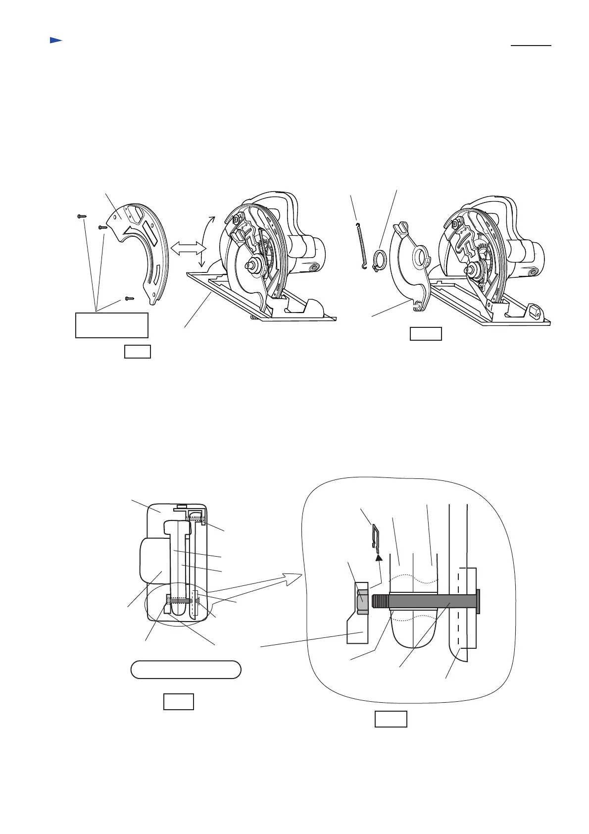
( 3 ) Base and the motor section is fixed with pin 10 and cap square neck bolt M8x98 as illustrated in Fig. 2.
Take off ring spring 12 from lever 54, and disassemble lever 54 together with hex nut M8
from cap square neck bolt M8x98 as illustrated in Fig.2A. Then, cap square neck bolt M8x98 can be
separated from the base section. Thus, the motor section has been made free from depth guide.
Tapping screws
CT 4x20
Pull base down to the minimum
cutting depth.
Tension
spring 4
Retaining ring S-40
Safety cover
Fig.1A
Base
Motor
section
Lever 54
Cap square
neck bolt M8x98
Hex nut M8
Pin 10
Fig. 2
Handle L
Handle R
Depth guide
Depth guide
Ring spring 12
Cap square
neck bolt M8x98
Hex nut M8
Handle L
Handle R
Top view of Mod.5705R
Pipe 9
Fig.2A
< Note > Take same step, when disassembling and assembling switch section.
 Loading...