11 ENGLISH
1
4
6
5
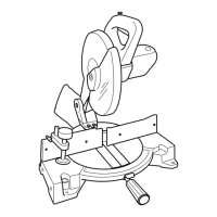
► 1. Left bevel cut 2. Straight cut 3. Right bevel cut
4. Saw blade 5. Blade teeth 6. Kerf board
First, unplug the tool. Loosen all the screws (2 each
on left and right) securing the kerf boards until the kerf
boards can still be easily moved by hand. Lower the
handle fully, then pull and turn the stopper pin to lock
the handle in the lowered position. Release the stopper
pin on the sliding pole and pull the carriage toward you
fully. Adjust the kerf boards so that the kerf boards just
contact the sides of the blade teeth. Tighten the front
screws (do not tighten rmly). Push the carriage toward
the guide fence fully and adjust the kerf boards so that
the kerf boards just contact the sides of blade teeth.
Tighten the rear screws (do not tighten rmly).
After adjusting the kerf boards, release the stopper
pin and raise the handle. Then tighten all the screws
securely.
NOTICE: After setting the bevel angle ensure
that the kerf boards are adjusted properly. Correct
adjustment of the kerf boards will help provide proper
support of the workpiece minimizing workpiece tear
out.
Maintaining maximum cutting
capacity
This tool is factory adjusted to provide the maximum
cutting capacity for a 305 mm saw blade.
When installing a new blade, always check the lower limit
position of the blade and if necessary, adjust it as follows:
First, unplug the tool. Turn the stopper lever to engaged
position.
1
► 1. Stopper lever
Push the carriage toward the guide fence fully and
lower the handle completely.
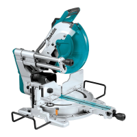
Adjust the blade position by turning the adjusting bolt
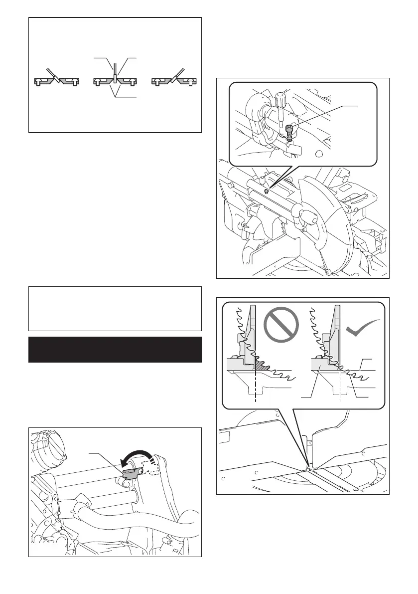
with the hex wrench. The periphery of the blade should
extend slightly below the top surface of the turn base
and also comes to the point where the front face of the
guide fence meets the top surface of the turn base.
1
► 1. Adjusting bolt
1
3
2
► 1. Top surface of turn base 2. Periphery of blade
3. Guide fence
With the tool unplugged, rotate the blade by hand while
holding the handle all the way down to be sure that
the blade does not contact any part of the lower base.
Re-adjust slightly, if necessary.
After adjustment, always return the stopper lever to the
original position.
 Loading...