Electrical System Section 6
6-4 Part No. 80-1100-3
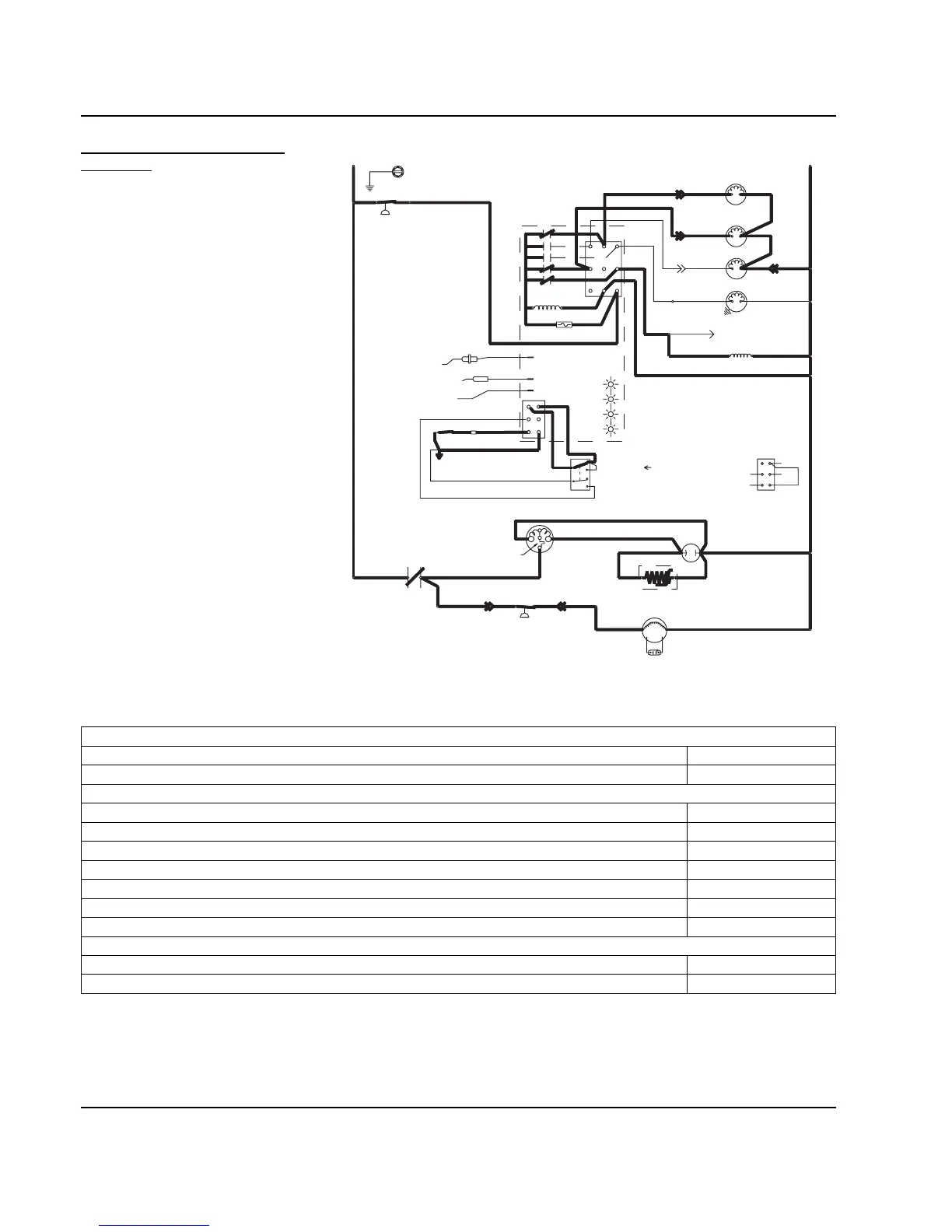
2. REFRIGERATION SYSTEM
START-UP
The compressor starts after the 45-
second water purge, and it remains
on throughout the Freeze and
Harvest cycles.
The water fill valve is energized at
the same time as the compressor. It
remains on until the water level
sensor closes for 3 continuous
seconds.
The harvest valve(s) remains on for
the first 5 seconds of the initial
compressor start-up.
At the same time the compressor
starts, the condenser fan motor (air-
cooled models) is supplied with
power. It continues to be supplied
with power throughout the Freeze
and Harvest cycles.
The fan motor is wired through a fan
cycle pressure control, and may
cycle on and off. (The compressor
and the condenser fan motor are
wired through the contactor. Any time
the contactor coil is energized, these
components are supplied with
power.)
Figure 6-2. Self-Contained — Refrigeration System Start-Up
Table 6-2. Self-Contained Models
2. Refrigeration System Start Up (5 Seconds)
Toggle Switch ICE
Bin Switch Closed
Control Board Relays
#1 Water Pump Open / OFF
#2 Water Fill Valve Closed / ON
#3 Harvest Solenoid Closed / ON
#4 Water Dump Valve Open / OFF
#5 Contactor Coil Closed / ON
Compressor ON
Condenser Fan Motor ON
Safety Controls (Which could stop ice machine operation)
High Pressure Cut-Out Closed
Main Fuse (On Control Board) Closed
*OVERLOAD
FAN CYCLE CONTROL
BIN SWITCH
TB35
TB33
(52)
(51)
(48)
CONTACTOR
CONTACTS
L1
(42)
(66)
(64)
ICE THICKNESS PROBE
WATER LEVEL PROBE
NOT USED
 Loading...