5
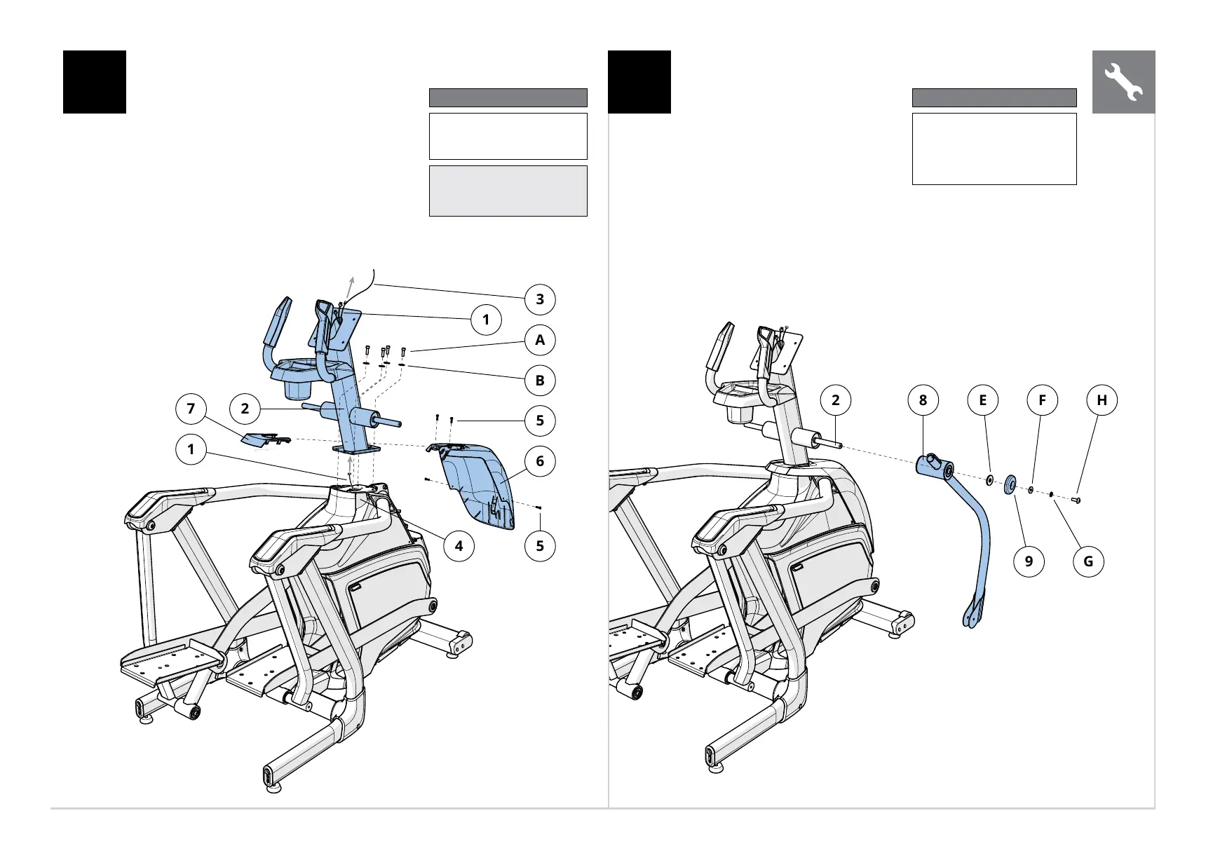
A Open HARDWARE FOR STEP 1.
B Remove 4 PRE-INSTALLED SCREWS (5) and
TOP CAP COVER (6)from MAIN FRAME (4).
C Carefully pull the CABLE (1) through the
CONSOLE MAST (2) using the LEAD WIRE
(3) located inside the CONSOLE MAST (2).
D Attach CONSOLE MAST (2) to MAIN
FRAME (4) using 4 BOLTS (A) and 4 FLAT
WASHERS (B). Tighten to 40 Nm / 29 lb-ft.
E Attach the TOP CAP COVER (6) to the MAIN
FRAME (4) using 4 PRE-INSTALLED SCREWS (5).
F Attach the CONSOLE MAST BOOT (7) to the
TOP CAP COVER (6) by snapping it into place.
1 2
A Open HARDWARE FOR STEP 2.
B Slide LOWER DUAL ACTION ARM
(8) onto the CONSOLE MAST (2)
C Attach using 1 FLAT WASHER
(E), 1 HANDLEBAR CAP (9), 1
FLAT WASHER (F), 1 SPRING
WASHER (G) and 1 BOLT (H).
Tighten to 40 Nm / 29 lb-ft.
D Repeat on other side.
Hardware For Step 3
Description Qty
E
F
G
H
Flat Washer (26 mm)
Flat Washer (19 mm)
Spring Washer
Bolt
2
2
2
2
Hardware For Step 1
Description Qty
A
B
Bolt
Flat Washer
4
4
Note: Be careful not to pinch
any wires while attaching the
upper assembly.
ENGLISH