1B
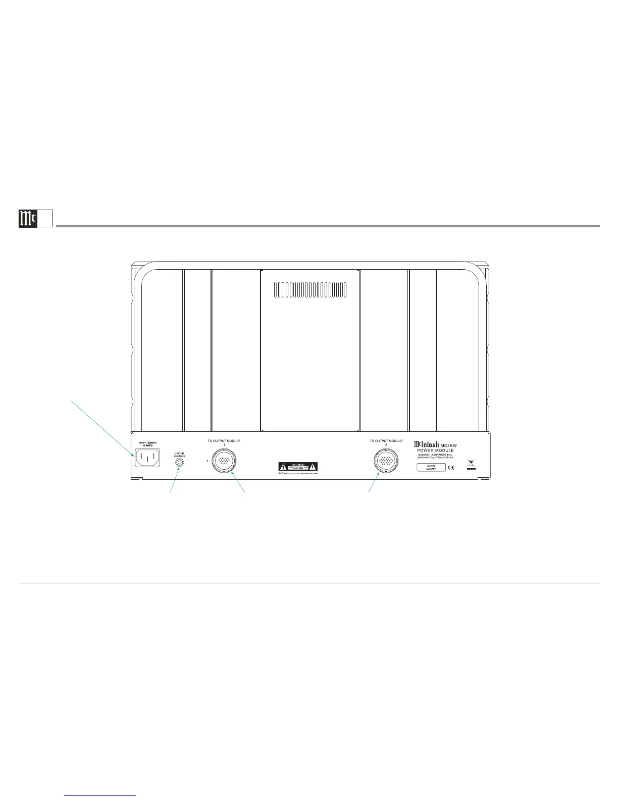
MC2KW Power Module Rear Panel Connections
Connect the MC2KW Power Module
power cord to a dedicated live AC
Circuit with Outlet1. Refer to informa-
tion on the back panel of the MC2KW
Power Module to determine the cor-
rect voltage for your unit.
1
Each of the MC2KW Power
Modules needs to be connected
to a dedicated AC Circuit with
Outlet. Refer to “Important
Information” note 6 on page 4 in
this Owner’s Manual for addi-
tional information.
CIRCUIT BREAKER
Press to reset if the
MC2KW Power Module
will not power up
MC2KW POWER MODULE (A or B)
2
Connector 1 accepts the custom McIn-
tosh 16 Conductor Cable. This cable at-
taches to the MC2KW OUTPUT MOD-
ULE (A or B )2 Connector 1. It connects
the power output signal of the MC2KW
POWER MODULE to the Autoformer
inside the MC2KW OUTPUT MODULE.
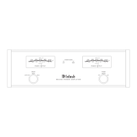
MC2KW OUTPUT MODULE (A or B)
2
Connector 2 accepts the custom McIntosh
21 Conductor Cable. This cable attaches
to the MC2KW OUTPUT MODULE (A
or B)2 Connector 2. It connects the input
signal, control and power supply voltages
from the MC2KW OUTPUT MODULE.
2
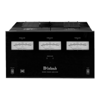
A MC2KW Power Amplifier consists
of one MC2KW Output Module and
two MC2KW Power Modules. The
first MC2KW Power Module is ref-
ered to as chassis “A” and the second
MC2KW Power Module is refered to
as chassis “B”. Both MC2KW Power
Modules “A” and “B” connect to the
same MC2KW Output Module.
WARNING: The Power Module Connectors 1 and 2 “To Output Module Terminals are hazardous live and present a risk of electric shock. Use ONLY the Custom Interconnect
Cables supplied with the MC2KW Output Module and MC2KW Power Module, refer to page 4 of the MC2KW Owner’s Manual for additional information.
 Loading...