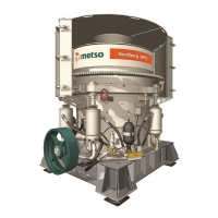
Do you have a question about the Metso HP5 and is the answer not in the manual?
| Brand | Metso |
|---|---|
| Model | HP5 |
| Category | Industrial Equipment |
| Language | English |
Emphasizes checking main frame liners during liner changes to prevent costly damage from neglect.
Periodically measure the distance between adjustment ring and main frame; replace seat liners when reduced by 8mm.
Provides steps for dismantling the oil chamber: removing drain plug, nuts, springs, seat, and possibly changing the chamber.
Steps for installing the clamping ring assembly: cleaning housing, engaging valves, positioning oil chamber, placing springs, and tightening nuts.
Further steps include applying grease, seating parts, ensuring correct orientation, and tightening/locking nuts to a specific spring length.
Provides instructions for cylinder installation, including rod pull-out distance based on crusher size (HP3, HP4, HP5).
Provides instructions for bushing installation, including cooling them in ice for 2 hours and using approximately 25 kg of ice.
Defines end float (clearance) for new HPs as 0.8 mm – 1.6 mm and shows components like Outer Countershaft Box Bushing, End Float, and Oil Flinger.
Describes using a feeler gauge and heating the oil flinger to ensure it's tight against the gauge for proper end float setting.
Provides steps for installing the eccentric bushing, including cooling with dry ice, using ring bolts, and aligning oil holes precisely.
Outlines the break-in procedure for new bushings, including temperature checks, operation without material, and phased loading.
Provides a table of backlash and root clearance specifications for HP3, HP4, and HP5 crushers.
Outlines socket installation steps: using centering/eye bolts, heating the socket, sliding it down, and securing with fixation bolts and torque checks.
Details head ball installation: cooling with dry ice for 4-6 hours, measuring bore/ball, and re-installing the safety bolt with Loctite 277.
Details bowl liner installation: contact on thin helix portion, vertical wedge bolt tightening, and spring washer torque control.
Details the function of the pressure switch in controlling minimum lubrication pressure (0.8 bars) and its role in preventing crusher damage.
Explains how to set the pressure switch, including adjusting red and green screws for specific bar values (1.1 bar, 0.3 bar differential).
Measures tramp release circuit pressure (0-400 bar) and converts it to a 4-20mA signal for automation.
Crusher is equipped with 2 Pt100 temperature sensors measuring lower thrust bearing and oil return line temperatures.
Sensors connect to converters sending 4-20 mA signals, with temperature-to-mA conversion ranges provided.