3
Schematic Plan for DP-9900plus/DP-9900/DP-9600 Part
Installation
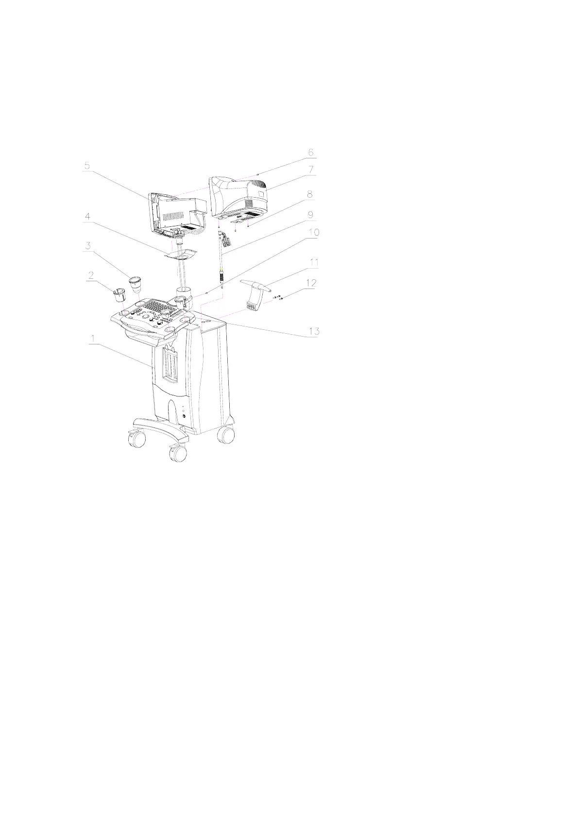
Figure 4 Schematic Plan of Part Installation
Operating procedures are shown as follows:
I. Installing the monitor
1. As shown in the figure, prior to installation of the monitor, place the neck cover on the neck of
the main unit, and place the friction pad on the rotating axis.
2. Thread the power cable and signal cable through the axis, and then place the rotating axis
into the axile bush. Connect the cables to the connectors, tighten the cables, and fix the
cables by the cable strap at the bottom of the monitor.
3. Install the rear cover of the monitor and tighten it with three M4X8 screws. Fix the neck cover
with screw M5×16 and spring washer Φ5.
1. main unit
2. transducer holder B
3. ultrasound gel holder
4. neck cover washer Φ5
5. monitor assembly
6. screw M4x8
7. rear cover of monitor
8. screw M4×8
9. transducer cable hook
10. limit screw M5×16/spring
washer Φ5
11. pushing handle
12. hexagon socket M5x35/spring
washer Φ5/plain washer Φ5
13. transducer holder A

 Loading...


