5
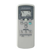
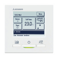
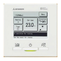
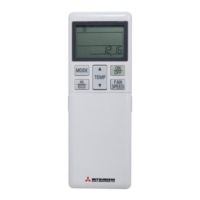
Wireless remote controller
5
Wireless remote controller (continued)
Installation tips for the remote controller holder
Fix the remote controller holder using the screws supplied
with this product.
* Precautions for installing the holder
Ɣ
Adjust the position so that it is upright.
Ɣ
Ensure that the screw heads are not protruding.
Ɣ
DO NOT attach the holder on plaster wall
How to insert batteries
1. Detach the back lid.
2. Insert the batteries. (two AAA batteries)
3. Reattach the back lid.
Setting to avoid mixed communication
1. Detach the back lid, and remove the batteries.
2. Cut off the switching wire in the battery compartment using nippers.
3. Insert the batteries, and attach the back lid.
Changing the remote controller setting
How to change the Auto Run setting
The Auto Run mode is not available on the building air conditioning and gas heat
pump series (excluding the cooling/heating free multi system).
When using the remote controller to operate those models, set the remote controller
to disable the Auto Run mode.
To disable the Auto Run mode, press the
ACL
switch while holding down the
MODE
button, or insert batteries while holding down the
MODE
button.
* Note: Once the batteries are removed, the setting is reset to the factory default.
When the batteries are removed, repeat the steps described above.
Indoor function settings
1. How to set indoor functions
1
Press the ON/OFF button to stop the unit.
2
Press the desired one of the buttons shown item 2. while holding down the
FUNCTION SETTING switch.
3
Use the selection buttons,
Ÿ
and
ź
, to change the setting.
4
Press the SET button.
The buzzer on the remote control signal receiver beeps twice, and the LED
lamp flashes four times at two-second intervals.
1
Control plural indoor units with one remote controller
Up to 16 indoor units can be connected.
1.
Connect the XY terminal with 2-core wire. As for the
size, refer to the following note.
2.
For Packaged air conditioner series, set the indoor
unit address with SW2 on the indoor unit PCB from
[0] to [F] so as not to duplicate.
For the shop series
For VRF series, set the indoor unit address with SW1, SW2 and SW5-2 on the indoor unit PCB from [000]
to [127] so as not to duplicate.
For the building air conditioning and gas heat pump series
Set the indoor unit and outdoor unit numbers by manually specifying the addresses.
Use the rotary SW1 and SW2 provided on the indoor unit PCB (printed circuit board) to set the indoor unit
numbers so that they are not duplicated.
Master/Slave setting when using plural remote controller
Up to two receivers can be installed in one indoor unit group.
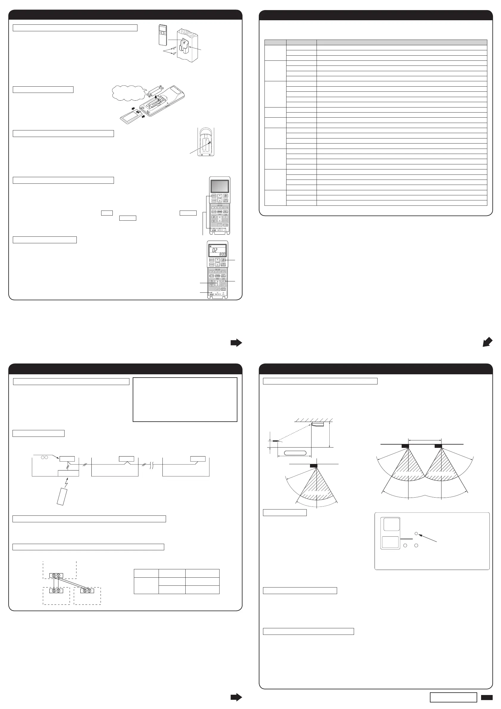
Wireless remote controller's operable area
Backup switch
A backup switch is provided on the receiver
section of the panel surface.
When operation from the wireless remote control
unit is not possible (due to flat batteries, a mislaid
unit, a unit failure), you can use it as an emergency
means. You should operate this switch manually.
1.
If pressed while the air conditioner is in a halt, it
will cause the air conditioner to start operation
in the automatic mode (in the case of cooling
only, in the cooling mode).
Wind speed: Hi fan, Temperature setting: 23°C,
Louver: horizontal.
2. If pressed while the air conditioner is in operation, it will stop the air conditioner.
Cooling test run operation
Ɣ
After safety confirmation, turn on the power.
Ɣ
Transmit a cooling operation command with the wireless remote control unit, while the backup switch
on the receiver is depressed.
Ɣ
If the backup switch on the receiver is pressed during a test run, it will end the test run.
Ɣ
If you cannot operate the unit properly during a test run, please check wiring by consulting with
inspection guides.
How to read the two-digit display
A two-digit indicator (7-segment indicator) is provided on the receiver section.
1. An indication will be displayed for one hour after power on.
2. An indication appears for 3.5 seconds when a Stop command is sent from the wireless remote
control unit while the air conditioner is not running.
3. An indication appearing in (1) or (2) above will go off as soon as the unit starts operation.
4. When there are no error records to indicate, addresses are displayed for all of the connected units.
5. When there are some error records remaining, the error records are displayed.
6. Error records can be cleared by transmitting a “Stop” command from the wireless remote control
unit, while the backup switch is depressed.
6
Receiver
6
Receiver (continued)
5
7
6
Wood screw
Cutting
Holder for
remote controller
Ensure the correct
polarity when
inserting.
Auto Run setting
1
4
2
3
Indoor unit
Receiver
SW1[Master]
Receiver
SW1[Slave]
Remote controller line
(Non-polarized)
Switch Setting Function
SW2
ON Master
OFF Slave
Restrictions on the thickness and length of wire
(Maximun total extension 600m.)
Standard Within 0.3 mm² × 100m
Within 0.5 mm² × 200m
Within 0.75mm² × 300m
Within 1.25mm² × 400m
Within 2.0 mm² × 600m
KIT
Remote controller
Indoor unit (1)
Address (0)
Indoor unit (2)
Address (1)
Indoor unit (16)
Address (F)
X Y
60°
5m
Receivable range
(Top view)
8
PFA012 D635
Backup switch
TIMER
CHECK RUN
1. Standard signal receiving range
[Condition]
Illuminance at the receiver area: 360 lux.
(When no lighting fixture is located within 1m
of indoor unit in an ordinary office)
2. Points for attention in connecting a plural
number of indoor units
[Condition]
Illuminance at the receiver area: 360 lux.
Wireless remote
control unit
1m
2.4m
Within 5m
Floor surface
Ceiling surface
(Top view)
60°
5m
5m
60°
5m
Receivable range
Receivable range
2. Setting details
The following functions can be set.
Button Number indicator Function setting
FAN SPEED
00 Fun speed setting : Standard
01 Fun speed setting : Setting 1 *
02 Fun speed setting : Setting 2 *
MODE
00 Room heating temperature adjustment : Disable
01 Room heating temperature adjustment : +1°C
02 Room heating temperature adjustment : +2°C
03 Room heating temperature adjustment : +3°C
FILTER
00 Filter sign display : OFF
01 Filter sign display : 180 hours
02 Filter sign display : 600 hours
03 Filter sign display : 1000 hours
04 Filter sign display : Operation stop after 1000 hours have elapsed
U/P
(Up/Down)
00 Anti draft setting : Disable
01 Anti draft setting : Enable
SILENT
00 Infrared sensor setting (Motion sensor setting) : Disable
01 Infrared sensor setting (Motion sensor setting) : Enable
HI POWER
00 Infrared sensor control (Motion sensor control) : Disable
01 Infrared sensor control (Motion sensor control) : Power control only
02 Infrared sensor control (Motion sensor control) : Auto OFF only
03 Infrared sensor control (Motion sensor control) : Power control + Auto OFF
ON TIMER
00 Cooling fan residual-period running : Disable
01 Cooling fan residual-period running : 0.5 hours
02 Cooling fan residual-period running : 2 hours
03 Cooling fan residual-period running : 6 hours
OFF TIMER
00 Heating fan residual-period running : Disable
01 Heating fan residual-period running : 0.5 hours
02 Heating fan residual-period running : 2 hours
03 Heating fan residual-period running : 6 hours
NIGHT
SETBACK
00 Remote control signal receiver LED : Brightness High
01 Remote control signal receiver LED : Brightness Low
02 Remote control signal receiver LED : OFF
* Refer to technical data.
300
300
 Loading...