FX
2N
-10GM
USER’S GUIDE
JY992D77701B
This manual only describes the specifications for FX
2N
-10GM positioning controller.
For complete operation, wiring, mounting and programming instructions please refer to the FX
2N
-10GM,
FX
2N
-20GM HARDWARE PROGRAMMING MANUAL, FX PROGRAMMING MANUAL and FX SERIES
HARDWARE MANUAL.
These manuals should be read and understood before attempting to install or use the unit.
1. Reference manual
Refer to the under mentioned manual for details about product installation, and programming.
1) FX
2N
-10GM, FX
2N
-20GM HARDWARE PROGRAMMING MANUAL
The installation of FX
2N
-10GM and FX
2N
-20GM and wiring and the instructions are explained.
2) E-20TP OPERATION MANUAL
The operation of the input of the program which uses E-20TP and the monitor and the test is
explained.
3) FX-PCS-KIT-GM-EE SOFTWARE MANUAL
The program is input via the FX-PCS-KIT-GM-EE. The manual explains the operation of the monitor
and test functions.
The manual in 1) is not included with the product. Please request from the shop where the units was pur-
chased if required.
The manuals in 2) and 3) are included with the product.
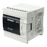
2. Outline of the unit
The FX
2N
-10GM positioning controller (hereinafter call FX
2N
-10GM or 10GM) is a pulse chain output unit
that enables the positioning control of a stepping motor or a servo motor via the drive unit.
•One FX
2N
-20GM can control 2 axes.
• Both dedicated positioning language (cod instructions) and sequence language (basic instructions
and application instructions) are available.
• A pulse generator can be connection.(The manual pulse generators must be an open collector output
type.)
• The zero return operation at each start can be omitted with a servo amplifier with the absolute position
(ABS) detection function.
• The FX
2N
-10GM can be used alone. When an FX
2N
-10GM is connected with an FX
2N
or FX
2NC
series Programmable controller (here after call PLC), reading and writing the positioning data can be
done. (When FX
2N
-10GM is connected with the FX
2NC
series PLC, an FX
2NC
-CNV-IF is necessary.)
3. External dimensions
ZRN
FWD
Y4
Y5
RP
STOP
FP
X2
X3
Y0
Y1
Y2
START
Y3
CLR
AUTO
MANU
POWER
READY
ERROR
CPU-E
X0
RVS
DOG
LSF
LSR
X1
PGO
SVRDY
SVEND
FX -10GM
2N
90(3.54)
60(2.36)
13
(0.51)
74(2.91)
13(0.51)
87(3.43)
Power supply
cable
Din rail width: 35mm
Weight: approx.0.3kg
Dimensions mm(inch)
4. Product composition
4.1 Each part name
The name and description of each part of the FX
2N
-10GM are explained below.
➀
Operation indicator LED
➁
MANU/AUTO switch
➂
Connector for programming tool
➃
I/O display
➄
Connector for PLC extension block
➅
Hook for DIN rail installation
➆
Connector for motor amplifier: CON2
➇
Connector for I/O: CON1
➈
Connector for power supply
➉
Connector for PLC
ZRN
FWD
Y4
Y5
RP
STOP
FP
X2
X3
Y0
Y1
Y2
START
Y3
CLR
AUTO
MANU
POWER
READY
ERROR
CPU-E
X0
RVS
DOG
LSF
LSR
X1
PGO
SVRDY
SVEND
FX -10GM
2N
➀➃
➈
➇
➆
➅
➂➁
➄
Accessories
Power supply cable
FX
2NC
-100MPCB 1
Connection cable
FX
2N
-GM-5EC 1
➉
➅
4.2 Operation display
The state of FX
2N
-10GM is displayed by LED.
Name of LED Content
POWER
LED lights when power is supplied. If LED is not lit, check power supply voltage and
current.
READY
LED lights when accepting an axis instruction.
During pulse output or when an error occurs, the LED is off.
ERROR LED is lit or blinks when an error occurs in the positioning drive of FX
2N
-10GM.
CPU-E
CPU error. Incompatible system configuration, excess noise, etc. (Mixing foreign body,
and influence of noise, etc.)
4.3 I/O connector
The pin array of the I/O connector is as follows.
All terminals with identical names are shorted internally. (Ex. COM1-COM1, VIN-VIN, etc.)
Do not wire “
•
“ terminals.
Refer to the FX
2N
-10GM, FX
2N
-20GM HARDWARE PROGRAMMING MANUAL for wiring information.
CON1
X1
X0
X2
X3
Y0
Y1
Y2
Y3
COM1
COM2
SVRDY
CLR
COM3
FP
VIN
VIN
COM5
ST1
CON2
COM2
SVEND
PG0
COM4
RP
VIN
VIN
COM5
ST2
STOP
START
ZRN
FWD
RVS
DOG
LSF
LSR
COM1
Y4
Y5
4.4 Power supply connector
The power to the FX
2N
-10GM is supplied with the special power supply cable attached to the product.
The ground of the FX
2N
-10GM and the servo amplifier is a common ground. Refer to the FX
2N
-10GM,
FX
2N
-20GM HARDWARE PROGRAMMING MANUAL for details wiring instruction.
Black
Red +
Green
(Ground)
FX
2NC
-100MPCB
FX
2N
-10GM
1
3 Ground
2
-
The pin number of the
power supply connector
of FX
2N
-10GM
Install a safety circuit outside of
FX
2N
-10GM so that the entire
system may work safety when
the external power supply fails.
4.5 Connection with PLC
Refer to the FX
2N
-10GM, FX
2N
-20GM HARDWARE PROGRAMMING MANUAL for details concerning the
system configuration.
The FX
2N
-GM-5EC cable is used to connect the FX
2N
-10GM to an FX
2N
PLC. When along distance is
required, one FX
2N
-GM-65EC cable can be used per system. To connect to an FX
2NC
PLC, the FX
2NC
-
CNV-IF must be used. Eight blocks may be connected to an FX
2N
PLC
and four blocks may be connected
to an FX
2NC
PLC.
FX
2NC
PLC
Main unit
FX
2NC
-CNV-IF FX
2N
-10GM
FX
2N-
GM-5ECFX
2NC
-16EX
(I/O Extension of main
unit of the PLC)