FX
2N
-2DA SPECIAL FUNCTIONBLOCK
USER’S GUIDE
JY992D74901C
This manual contains text, diagrams and explanations which will guide the reader in the correct installation
and operation of the FX
2N
-2DA special function block and should be read and understood before
attempting to install or use the unit.
Further information can be found in the FX SERIES PROGRAMMING MANUAL,FX
2N
SERIES
HARDWARE MANUAL of each PLC.
1. INTRODUCTION
The FX
2N
-2DA type analog output block (Hereafter referred to as the FX
2N
-2DA) is used to convert a
digital value of 12 bits into an analog output of two points (voltage output and current output), and to
forward the values to the Programmable controller (Hereafter referred to as a PLC).
FX
2N
-2DA can be connected with FX
0N
, FX
1N
, FX
2N
, and the FX
2NC
series Programmable controllers.
1) The analog out put is selected from the voltage output or the current output by the method of
connecting wires.
At this time, assume setting to be two channels common analog output.
2) The two analog output channels can accept output of 0 to 10V DC, 0 to 5V DC, or 4 to 20mA.
(The mixture use for the voltage output/the current output is possible.)
3) Resolution is 2.5mV (0 to 10V DC) and 4
µ
A(4 to 20mA).
4) The digital to analog conversion characteristics can be adjusted.
5) The block occupies 8 I/O points which can be allocated from either inputs or outputs.
6) The data transfer with the PLC uses the FROM/TO instruction.
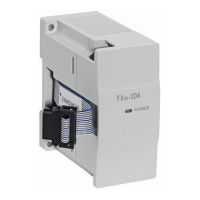
2. EXTERNAL DIMENSIONS AND PARTS
Dimensions: mm (inches)
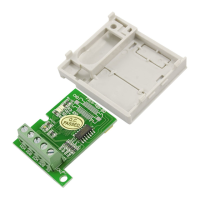
3. WIRING
*1 Connect a 0.1 to 0.47
µ
F 25V DC capacitor with the position of *1 when there is voltage
ripple in the voltage output or there will be a lot of noise.
*2 For voltage output please short circuit IOUT and COM as shown in the diagram.
DIN rail
mounting
slot
35mm(1.38)
Mounting
holes
2holes4.5
(0.18)dia
Extension
cable
43(1.69)
80(3.15)
87(3.43)
9(0.35)
4(0.16)
90(3.54)
M3(0.12)
terminal screws
OFF SET/GAIN
volume
Mass (Weight):0.2kg (0.44lbs) Accessories: Exchange number label
*1
VOUT
IOUT
COM
VOUT
IOUT
COM
Extension
cable
PLC
DC/DC
converter
+15V
-15V
AG
Inverter
etc
Recorder
etc
*3
Current output
Voltage output
FX
2N
-2DA
*3 Channel number enter
*2
4. CONNECTION WITH PROGRAMMABLE CONTROLLER
1) Up to 4 FX
2N
-2DA units can be connected to an FX
0N
series PLC, up to 5 for FX
1N,
up to 8 for FX
2N
or,
up to 4 for an FX
2NC
series PLC, all with powered extension units.
However the following limitation exists when undermentioned special function blocks are connected.
FX
2N
: Main unit and powered extension units of 32 points I/O or less. Consumption current available for
undermentioned special function blocks
≤
190mA
FX
2N
: Main unit and powered extension units of I/O 48 points or more. Consumption current available
for undermentioned special function blocks
≤
300mA
FX
2NC
: Up to 4 undermentioned special function blocks can be connected regardless of the system I/O.
FX
0N/1N
:Main unit and powered extension units. Up to 2 undermentioned special function blocks can be
connected regardless of the system I/O.
The consumption of the above units is to be subtracted from the service power supply of the host
PLC.
2) The blocks occupy 8 points (The 8 points can be allocated from either inputs or outputs).
3) FX
2N
-2DA consumes 5V DC 30mA.
The total of 5V consumption of all special function blocks connected to an FX
2N
or FX
2NC
main unit or
an FX
2N
extension unit must not exceed the 5V source capacity of the system.
4) The FX
2N
-2DA and main unit are connected by a cable on the right of the main unit.
5. SPECIFICATIONS
5.1 Environment specification
Environmental specifications other than the above-mentioned are the same as the main unit of the
Programmable controller. (Refer to the manual of the Programmable controller)
5.2 Power supply specification and others
FX
2N
-2DA FX
2N
-2AD FX
0N
-3A
Consumption current of 24V DC for one unit 85mA 50mA 90mA
Item Content
Directric Withstand
voltage
500V AC 1min(Between analog output terminals and case)
Item Content
Analog circuits
24V DC
±
10% 85mA (Internal power supplied from the main unit)
Digital circuits 5V DC 30mA (Internal power supplied from main unit)
Isolation
Photo-coupler isolation between analog and digital circuits.
DC/DC converter isolation of power from main unit.
(No isolation between analog channels.)
Number of occupied
I/O points
The blocks occupy either 8 input or output points.
(can be either inputs or outputs)
72456130
1611 1514 1710 12 13
14 171510 12 13
72456130
1611
OUT
IN
L X13 X15
X10 X14 X16
24+N
COM X4
X7
Y4
Y5
Y6
COM3
Y10
Y11
Y12
Y13Y1
Y2
Y3
Y14
Y15
X3
X2
X1
POWER
BATT.V
RUN
CPU.E
PROG.E
FX
2N
-32MR
FX
2N
-2DA
FX
2N
-16EX
FX
2N
-2DA
FX
2N
-32ER
FX
2N
-2DA
POWER
2N
FX -2DA
POWER
2N
FX -2DA
POWER
2N
FX -2DA
1
IN 0
7
2
3
4
5
6
POWER
1
IN 0
7
2
3
4
5
6
X0
X5
72456130
72456130
OUT
IN
L X1X3X5X7
X6 X0 X2 X4 X6
24+N
COM X4
X7
COM4COM2
Y4
Y5
Y6
Y7 COM3
Y0
Y1
Y2
Y3COM1
Y0
Y1
Y2
Y3
Y4
Y5
Y6
Y7
X3
X2
X1
POWER
01234567
76543210
5.3 Defining gain and offset
6. ALLOCATION OF BUFFER MEMORY (BFM)
6.1 Buffer memory
BFM#16:The D/A conversion data of the channel specified with BFM#17 (digital value) is written.
The D/A data is written in the binary in order of subordinate position 8bit and high rank
4bit,divided into two portions.
BFM#17:b0•••The D/A conversion of CH2 begins by changing of 1
→
0.
b1•••The D/A conversion of CH1 begins by changing of 1
→
0.
b2•••The subordinate position eight bit data for the D/A conversion is held by changing of 1
→
0.
Write data in above-mentioned buffer memory by "8.Program example".
Item Voltage output Current output
Range of analog output
At shipping, the unit is adjusted to a digital range of 0 to 4000 for an analog
voltage output of 0 to 10V DC. When using FX
2N
-2DA by the current input or
the 0 to 5V DC output, it is necessary to readjust by the offset and gain
volumes.
0 to 10V DC, 0 to 5V DC
(External load resistance 2K to
1M
Ω
)
4 to 20mA
(External load resistance 400
Ω
or
less)
Digital input 12bit
Resolution 2.5mV(10V/4000) 1.25mV(5V/4000) 4
µ
A {(20-4)/4000}
Integrated accuracy ±1% (full scale 0 to 10V) ±1% (full scale 4 to 20mA)
Processing time 4ms/1 channel (sequence program and synchronization)
output characteristics
Only subordinate position 12bit becomes effective when the data of 13bit or
more is input, and high rank bit any more is disregarded.
Use a digital value within the range from 0 to 4095.
The output characteristic can be set to each two channels.
BFM
number
b15 to b8 b7 to b3 b2 b1 b0
#0 to #15 Reserved
#16 Reserved Current value of output data(8 bit)
#17 Reserved
D/A subordinate
position data
holding
CH1 D/A
conversion
beginning
CH2 D/A
conversion
beginning
#18 or more Reserved
Digital value
04000
10V
Analogue value
Digital value
Offset value is fixation
:0 to 10V
:0 to 4000
Analogue
value
10.238V
4095
Analogue
value
Digital value
04000
20mA
4mA
Analogue value
Digital value
:4 to 20mA
:0 to 4000
20.380mA
4095