Chapter 7 Setup
7–2
7-1 Setting the initial parameters
The servo parameters must be set to start up the servo drive system.
The servo parameters are input from the CNC. The input method will differ according to the CNC, so
refer to the Instruction Manual provided with each CNC.
7-1-1 Servo specification parameters
The servo specification parameters are determined according to the machine specifications and servo
system specifications.
No. Abbrev. Parameter name Explanation
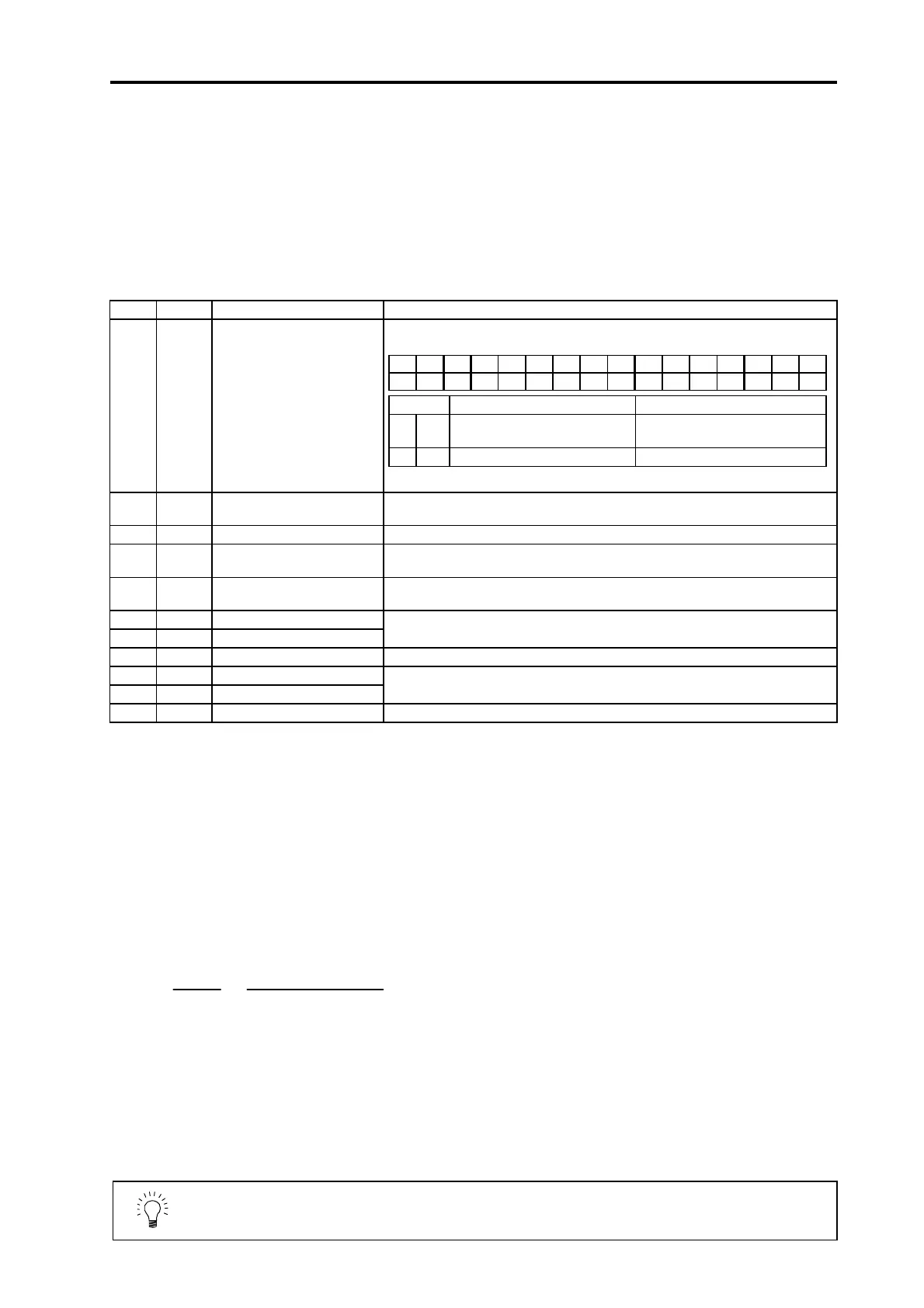
SV017 SPEC Servo specifications This is a HEX setting parameter. Set this as follows according to the servo
specifications.
SV025 MTYP Motor type Set the motor type.
Refer to the standard parameter list for each motor for the settings.
SV036 PTYP Regenerative resistor type Set 1000 as a standard.
SV027 SSF1 Special servo function
selection 1
Set 4000 as a standard.
SV033 SSF2 Special servo function
selection 2
Set 0000 as a standard.
SV001 PC1 Motor side gear ratio
SV002 PC2 Machine side gear ratio
Set the motor side gear ratio in PC1 and the machine side gear ratio in PC2.
When using a rotary axis, set the total deceleration (acceleration) ratio.
SV018 PIT Ball screw pitch Set the ball screw pitch with an mm unit. Set 360 for a rotary axis.
SV019 RNG1 Position detector resolution
SV020 RNG2 Speed detector resolution
Set the motor detector resolution with a kp/rev unit for both settings.
Refer to the standard parameters for each motor for the settings.
SV003 PGN1 Position loop gain Set 33 as a standard.
7-1-2 Limitations to electronic gear setting value
The servo amplifier has internal electronic gears. The command value from the NC is converted into
a detector resolution unit to carry out position control. The electronic gears are single gear ratios
calculated from multiple parameters as shown below. However, each value (ELG1, ELG2) must be
less than 32767.
If the value overflows, the initial parameter error (alarm 37) or error parameter No. 101 (2301 with
M50/M64 Series NC) will be output.
If an alarm occurs, the mechanical specifications and electrical specifications must be revised so that
the electronic gears are within the specifications range.
Reduced fraction of
ELG1
ELG2
=
PC2
×
RANG
PC1 × PIT × IUNIT
(reduced fraction)
RANG = RNG1 = RNG2
IUNIT = 2/NC command unit (µm)
1µm : IUNIT = 2, 0.1µm: IUNIT = 20
When the above is calculated, the following conditions must be satisfied.
ELG1 ≤ 32767
ELG2 ≤ 32767
POINT
If the electronic gears in the amplifier overflow, the alarm 37 or error
parameter No. 101 (2301 with M50/M64 series NC) will be output.
15 14 13 12 11 10 9 8 7 6 5 4 3 2 1 0
abs dmk
bit Meaning when "0" is set. Meaning when "1" is set.
0 dmk
Deceleration control stop
(Standard)
Dynamic brake stop selection
7 abs Incremental control Absolute position control
Set all bits other than those above to 0.
 Loading...