Chapter 7 Setup
7–3
7-1-3 Parameters set according to feedrate
The following parameters are determined according to each axis' feedrate.
No. Abbrev. Parameter name Explanation
SV023 OD1 Excessive error detection
width at servo ON
SV026 OD2 Excessive error detection
width at servo OFF
A protective function will activate if the error between the position command and
position feedback is excessive. If the machine load is heavy and problems occur
with the standard settings, gradually increase the setting value.
<Calculation of standard setting value>
OD1 = OD2 =
Rapid traverse rate (mm/min)
60
×
PGN1
÷ 2 (mm)
7-1-4 Parameters set according to machine load inertia
The following parameters are set according to the machine's inertia.
No. Abbrev. Parameter name Explanation
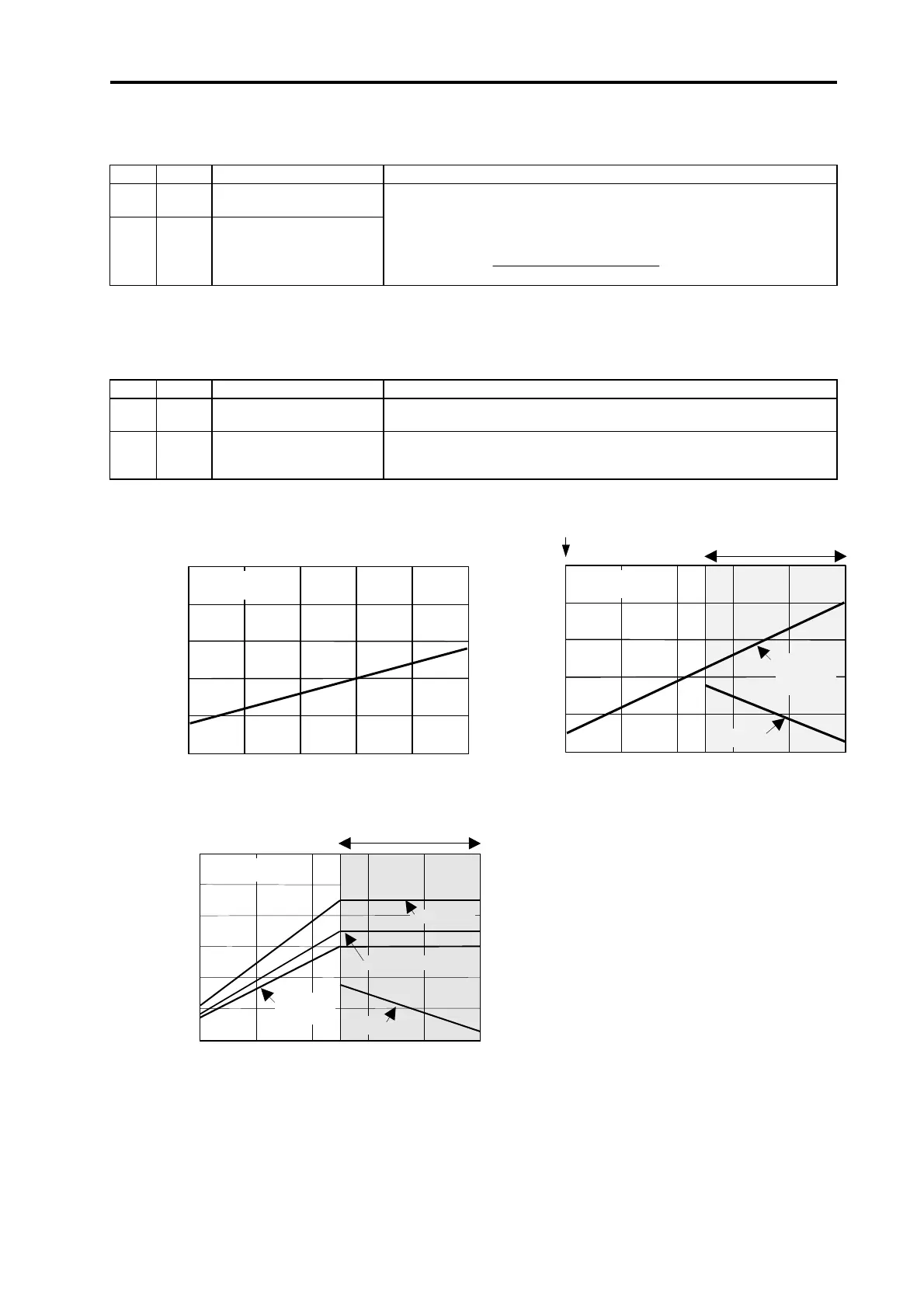
SV005 VGN1 Speed loop gain. Refer to the comparison graph with the load inertia scale for the standard setting
value.
SV008 VIA Speed loop leading
compensation
Set 1364 as a standard. Set 1900 as a standard for the SHG control.
If the load inertia is large and is in the standard VIA change region, set the value in
the comparison graph regardless of whether normal control or SHG control is used.
Load inertia scale (total load inertia/motor inertia)
Standard
VGN1
Motor single unit
1
3 7
11
5 9
<HS-RF>
HC-RF43
HC-RF73
1500
1000
500
VIA
VIA
Standard VIA change region
20
40
0
100
80
60
Load inertia scale (total load inertia/motor inertia)
Standard
VGN1
1
3 7
11
5 9
<HS-MF>
10
20
0
50
40
30
Load inertia scale (total load inertia/motor inertia)
Standard
VGN1
0
600
100
200
500
400
300
1500
1000
HC-SF52
HC-SF102
HC-SF202
500
VIA
VIA
<HC-SF>
HC-SF53, HC-SF103
Standard VIA change region
 Loading...