3
Mitsubishi Electric Melsec-Q Ethernet (UDP) Driver
2 Supported Device Addresses
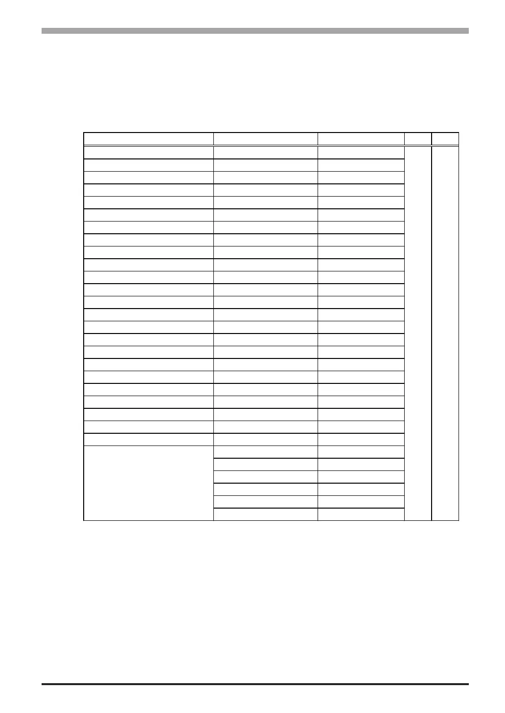
The following table lists the device address ranges you can enter from the Device Address
keypad. For actual device address ranges supported by the PLC, refer to the corresponding PLC
manual
Supported device addresses differ from protocol to protocol and between PLC models.
Device Bit Address Word Address 16 bit 32 bit
Input Relay X0000-XFFFF X0000-XFFF0
*1
Output Relay Y0000-YFFFF Y0000-YFFF0
*1
Internal Relay M00000-M65535 M00000-M65520
*2
Latch Relay L00000-L65535 L00000-L65520
*2
Special Relay SM0000-SM9999 SM0000-SM9984
*2
Annunciator F00000-F65535 F00000-F65520
*2
Edge Relay V00000-V65535 V00000-V65520
*2
Step Relay S0000-S9999 S0000-S9984
*2
Link Relay B0000-BFFFF B0000-BFFF0
*1
Special Link Relay SB000-SBFFF SB000-SBFF0
*1
Timer (contact) TS00000-TS65535 --
Timer (coil) TC00000-TC65535 --
Retentive Timer (contact) SS00000-SS65535 --
Retentive Timer (coil) SC00000-SC65535 --
Counter (contact) CS00000-CS65535 --
Counter (coil) CC00000-CC65535 --
Timer (current value) -- TN00000-TN65535
Retentive Timer (current value) -- SN00000-SN65535
Counter (current value) -- CN00000-CN65535
Data Register
*3
D00000:0-D65535:15 D00000-D65535
*4
Special Register
*3
SD0000:0-SD9999:15 SD0000-SD9999
*4
Link Register
*3
W0000:0-WFFFF:F W0000-WFFFF
*5
Special Link Register
*3
SW000:0-SWFFF:F SW000-SWFFF
*5
File Register(Normal)
*3
R00000:0-R65535:15 R00000-R65535
*4
0R0000:0-0R7FFF:F 0R0000-0R7FFF
*5
1R0000:0-1R7FFF:F 1R0000-1R7FFF
*5
2R0000:0-2R7FFF:F 2R0000-2R7FFF
*5
... ...
30R0000:0-30R7FFF:F 30R0000-30R7FFF
*5
31R0000:0-31R7FFF:F 31R0000-31R7FFF
*5
L/H
*6
L/H
*6
File Register(0R-31R)
*3
*1 To use as word address, the bit number (last digit) must be 0.
*2 To use as word address, must be multiple of 16.
*3 When the bit write operation is performed, the Target Machine reads the PLC’s
corresponding word address and turns a bit ON, then send back to PLC. Do not write to the
word address from the ladder program in the middle of this operation.
*4 You can define a bit address by adding a colon followed by the bit position (0~15) at the end
of the word. (e.g. D0000:15)
*5 You can define a bit address by adding a colon followed by the bit position (0~F) at the end
of the word. (e.g. W0000:F)
 Loading...