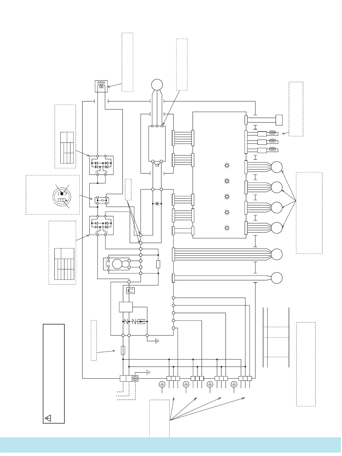
Power source
1 Phase
220/230/240V 50Hz
Unit
A
Unit
B
Unit
D
Unit
C
L
1
2
3
1
2
3
1
2
3
1
2
3
Fuse
250V 30A
CT
PCB (POWER)
BK
WH
BK
WH
RD
PK
BL
Y
R
1
S
1
G
Y
SA
S-A S-B S-C S-D COM
1
Y/
GN
Y/
GN
N
NF
P
1
N
1
R12
R
4
R
2
RY
1
RY
2
R
3
DS
1
DS
2
Re
CM
C
Y
Y
Y
S
2
GR
OR Y
RD
RD
BK
BK
6
1
2
0
4
1
+
RD
BL
+
–
+
–
P
N
W
V
U
RD
Power transistor
BK
BL
WH
P
2
N
2
WH
RD
CNCCNB CNN CNLCNKCNMCND
PCB (POWER TRANSISTOR)
Mark
Color mark
Color
CNN CNLCNKCNM
LED
1
A
LED
4
D
LED
5
ERROR
LED
3
C
LED
2
B
CND
CNS CNT CNU CNV CNR
51C
CNF
Th
O-R
Th
O-D
Th
O-A
PCB (CONTROL)
EEV
A
FM
O
20S
EEV
B
EEV
C
EEV
D
BK
BL
GR
OR
PK
Black
Blue
Grey
Orange
Pink
Mark Color
RD
WH
Y
Y/GN
Red
White
Yellow
Yellow/Green
52
X
5
52
X
5
●
Inspection of resistance value of discharge-
pipe thermistor.
Remove the connector and check the resistance value.
See the section of thermistor characteristics on page 109.
●
Inspection of electronic expansion valve
To test if there is voltage.
(Voltage is only applied to the electronic expansion valve when the valve angle is
being changed.)
Red to white
Red to Orange
Brown to yellow
Brown to blue
If the expansion valve does not operate as shown above, it is defective.
Normal if there is approximately DC 5 V 10 seconds
after the power supply is turned on.
}
●
Display lamp inspection
•
LED 5 (Abnormality display lamp - Red)
•
LED 1 to 4: (Light display for each room -
Green)
ON or flashing: Protection function operating)
ON when there is a serial signal being
received among each of the indoor units.
OFF during ignition, stop (including no
connection), abnormality
*
Tester probe
∞
Normal
condition
,
+ (RD)
+ (RD)
~ (OR)
~ (GR)
.
+ (OR)
+ (GR)
–
(BK)
–
(BK)
(When tester probes
are inverted, the read-
ing should be approx.
10~20
Ω
.)
●
Inspection of diode stack (DS1)
Tester probe
∞
Normal
condition
,
+ (BL)
+ (BL)
.
~ (RD)
~ (RD)
(When tester probes
are inverted, the read-
ing should be approx.
10~20
Ω
.)
●
Inspection of diode stack (DS2)
.
mark
Tester probe
(BK)
Tester probe
(RD)
●
Inspection of capacitor
Check the charging characteristics
with a tester. (Needle should
swing and return slowly. Change
the polarity and check again. If
the needle returns, it is normal.)
●
Power supply and serial
signal inspection
1
to
2
: AC220/240V
2
to
3
:
Normal if the voltage oscil-
lates between DC 0 and
approx. 12V
●
Inspection of reactor conductivity
Remove the connector and check for conductivi-
ty. It must be conductive.
●
Inspect power transistor.
Remove the fasten terminal and test out-
put voltage.
*
Check fuse. There should be conductivity.
Approx. DC 280 V
supply on.
 Loading...