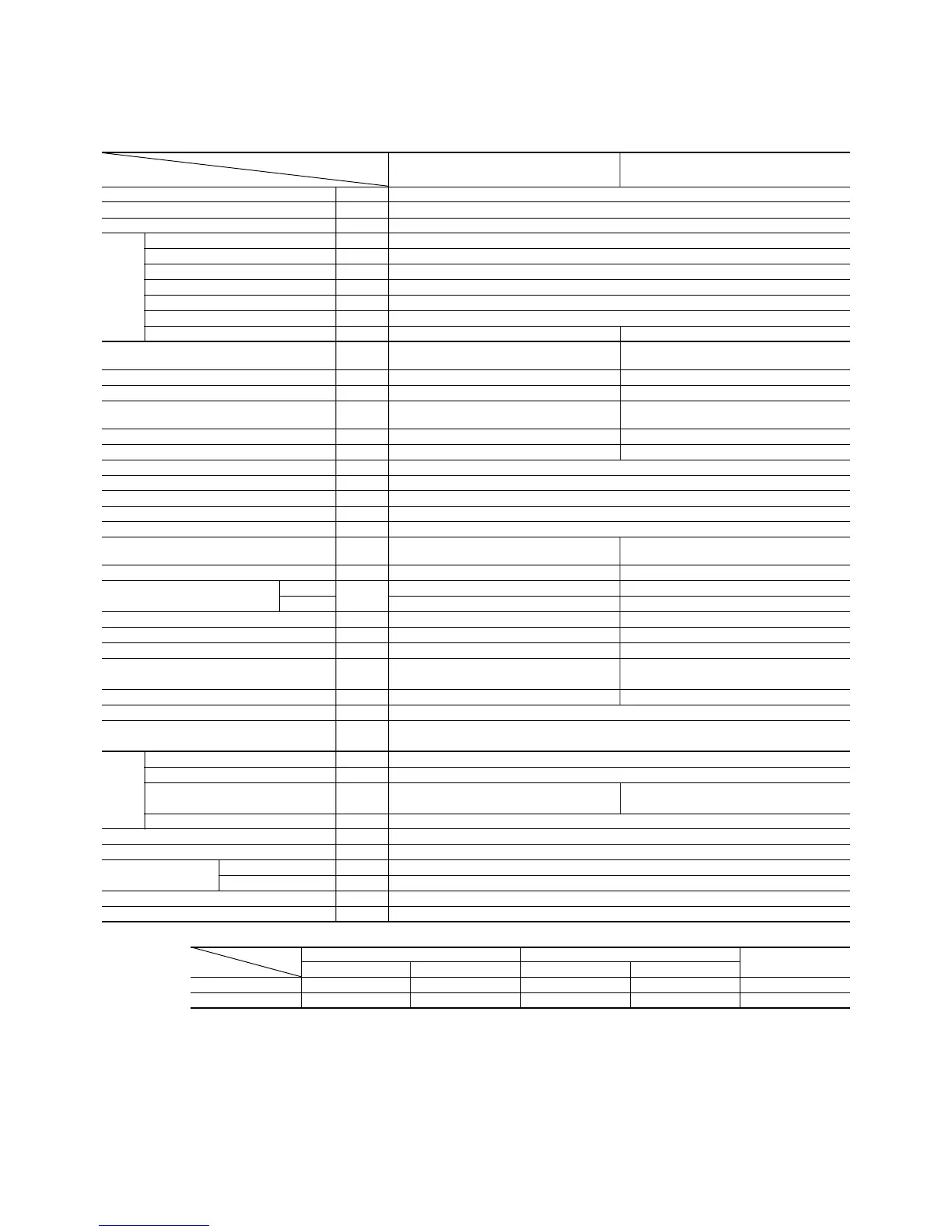
1-22
Item
Model
SRK35GZ-L1 SRC35GZ-L1
Cooling capacity
(1)
W 3650 [900~3900]
Heating capacity
(1)
W 4800 [900~6100]
Power source 1 Phase, 220/240V, 50Hz
Cooling input kW 1.24 [0.35~1.60]
Running current (Cooling) A 6.3
Heating input kW 1.52 [0.35~2.10]
Running current (Heating) A 7.7
Inrush current A 7.7
COP (Cooling) 2.94
Noise level dB (A) Cooling: 39 Heating: 42 Cooling: 46 Heating: 47
Exterior dimensions
Height × Width × Depth mm
275 × 790 × 174 542 × 795 × 255
Color Ivory white Polar white
Net weight kg 8 35
Refrigerant equipment
Compressor type & Q’ty
– RM5485GAE3 [Rotary type] × 1
Motor kW – 0.75
Starting method – Line starting
Heat exchanger Louver fins & bare tubing
Refrigerant control Capillary tubes
Refrigerant
(4)
kg R22 1.1 (Pre-Charged up to the piping length of 5m)
Refrigerant oil R 0.35 (BARREL FREEZE 32SAM)
Deice control MC control
Air handling equipment
Fan type & Q’ty
Tangential fan × 1 Propeller fan × 1
Motor W 16 18
(Cooling) 7 24
Air flow (at High)
(Heating)
CMM
10 24
Air filter, Q’ty
Polypropylene net (washable)
×
2
–
Shock & vibration absorber – Cushion rubber (for compressor)
Electric heater ––
Operation control
Operation switch
Wireless-Remote controller –
Room temperature control MC. Thermostat –
Pilot lamp RUN (Green), TIMER (Yellow)
Safety equipment
O.D mm (in) Liquid line: φ6.35 (1/4″) Gas line: φ12.7 (1/2″)
Connecting method Flare connecting
Attached length of piping Liquid line: 0.4 m
Gas line : 0.35 m
–
Insulation Necessary (Both sides)
Drain hose Connectable
Power source cord 2.5 m (3 cores with Earth)
Size × Core number 1.5 mm
2
× 4 cores (Including earth cable)
Connection wiring
Connecting method Terminal block (Screw fixing type)
Accessories (included) Mounting kit
Optional parts –
Notes (1) The data are measured at the following conditions.
Model SRK35GZ-L1 (Indoor unit)
SRC35GZ-L1 (Outdoor unit)
Item Indoor air temperature Outdoor air temperature
Standards
Operation DB WB DB WB
Cooling 27ºC 19ºC 35ºC 24ºC JIS C9612, ISO-T1
Heating 20ºC – 7ºC 6ºC JIS C9612, ISO-T1
(2) The values for performance and power consumption shown in brackets [~] indicate the range from minimum to maximum.
(3) The operation data are applied to the 220/240V districts respectively.
(4) Limitation of Voltage application Minimum: 198V Maximum: 264V
(5) The refrigerant quantity to be charged includes the refrigerant in 5 m connecting piping.
(Purging is not required even in the short piping.)
If the piping length is longer,
(When it is 5 to 15 m, add 20 g refrigerant per meter.)
Operation data
(1)
Refrigerant
piping
Compressor: Overheat protection, heating overload protection (High pressure control), overcurrent
protection, frosting protection, serial signal error protection, indoor fan motor error protection
 Loading...