1-20
(2) The operation data are applied to the 220V, 230V or 240V districts respectively.
(3) The refrigerant quantity to be charged includes the refrigerant in 7 m connecting piping.
(Purging is not required even in the short piping.)
If the piping length is longer, (When it is 7 to 15 m, add 20 g refrigerant per meter.)
(4) When the unit is operated in cooling or dehumidification mode at the outside air temperature of 1ºC and less, there is a possibility that water leakage
occurs at the indoor unit.
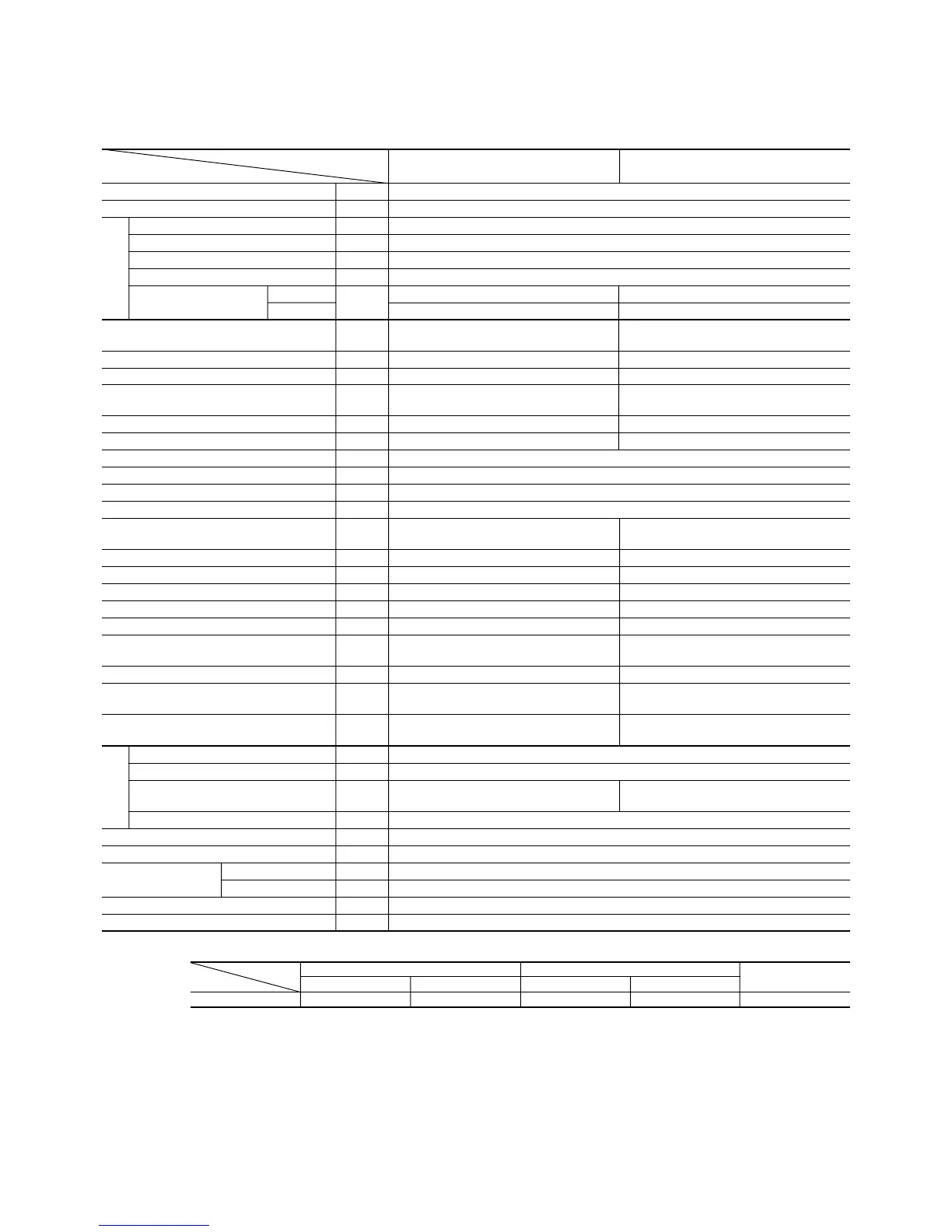
Notes (1) The data are measured at the following conditions.
Model SRK56A (Indoor unit)
SRC56CA (Outdoor unit)
Item Indoor air temperature Outdoor air temperature
Standards
Operation DB WB DB WB
Cooling 27°C19°C35°C24°C ISO-T1, JIS C9612
Item
Model
SRK56A SRC56CA
Cooling capacity
(1)
W 5000
Power source 1 Phase, 220/230/240V, 50 Hz
Cooling input kW 2.08
Running current (Cooling) A 9.7/9.3/8.7
Inrush current A 44/46/48
COP (In cooling) 2.40
Noise level
Sound level
dB
Hi : 45 Lo : 38 54
Power level Hi : 59 Lo : 52 68
Exterior dimensions mm
298 × 798 × 203 640 × 850 × 290
Height × Width × Depth
Color Noble white Stucco white
Net weight kg 10 44
Refrigerant equipment
– RM5526GNE4 (Rotary type) × 1
Compressor types & Q’ty
Motor kW – 1.9
Starting method – Line starting
Heat exchanger Louver fins & grooved tubing
Refrigerant control Capillary tubes
Refrigerant
(3)
kg R22 1.45
Refrigerant oil R 0.7 (BARREL FREEZE 32SAM)
Air handling equipment
Tangential fan × 1 Propeller fan × 1
Fan type & Q’ty
Motor W 23 35
Air flow (at High) CMM 11 39
Air filter, Q’ty Polypropylene net (washable) × 2–
Shock & vibration absorber – Cushion rubber (for compressor)
Electric heater ––
Operation control
Wireless-Remote controller –
Operation switch
Room temperature control MC. Thermostat –
Pilot lamp RUN (Green), TIMER (Yellow),
–
ECONO (Orange), HI POWER (Green)
Safety equipment
–
Dome mounted protector (for compressor)
Internal thermostat (for fan motor)
O.D mm (in) Liquid line: φ6.35 (1/4") Gas line: φ12.7 (1/2")
Connecting method Flare connecting
Attached length of piping Liquid line: 0.5m
–
Gas line : 0.43m
Insulation Necessary (Both sides)
Drain hose Connectable
Power source cord 3 m (3 cores with Earth)
Size × Core number 1.5 mm
2
× 3 cores (Including earth cable)
Connecting method Terminal block (Screw fixing type)
Accessories (included) Mounting kit
Optional parts –
Connection
wiring
Operation data
(1)
Refrigerant
piping
 Loading...