EasyManuals Logo
Home>Mitsubishi>Air Conditioner>SRC561HENF-L

Mitsubishi SRC561HENF-L User Manual

Mitsubishi SRC561HENF-L
68 pages
To Next Page IconTo Next Page
To Previous Page IconTo Previous Page
Page #42 background imageLoading...
Page #42 background image
1-42
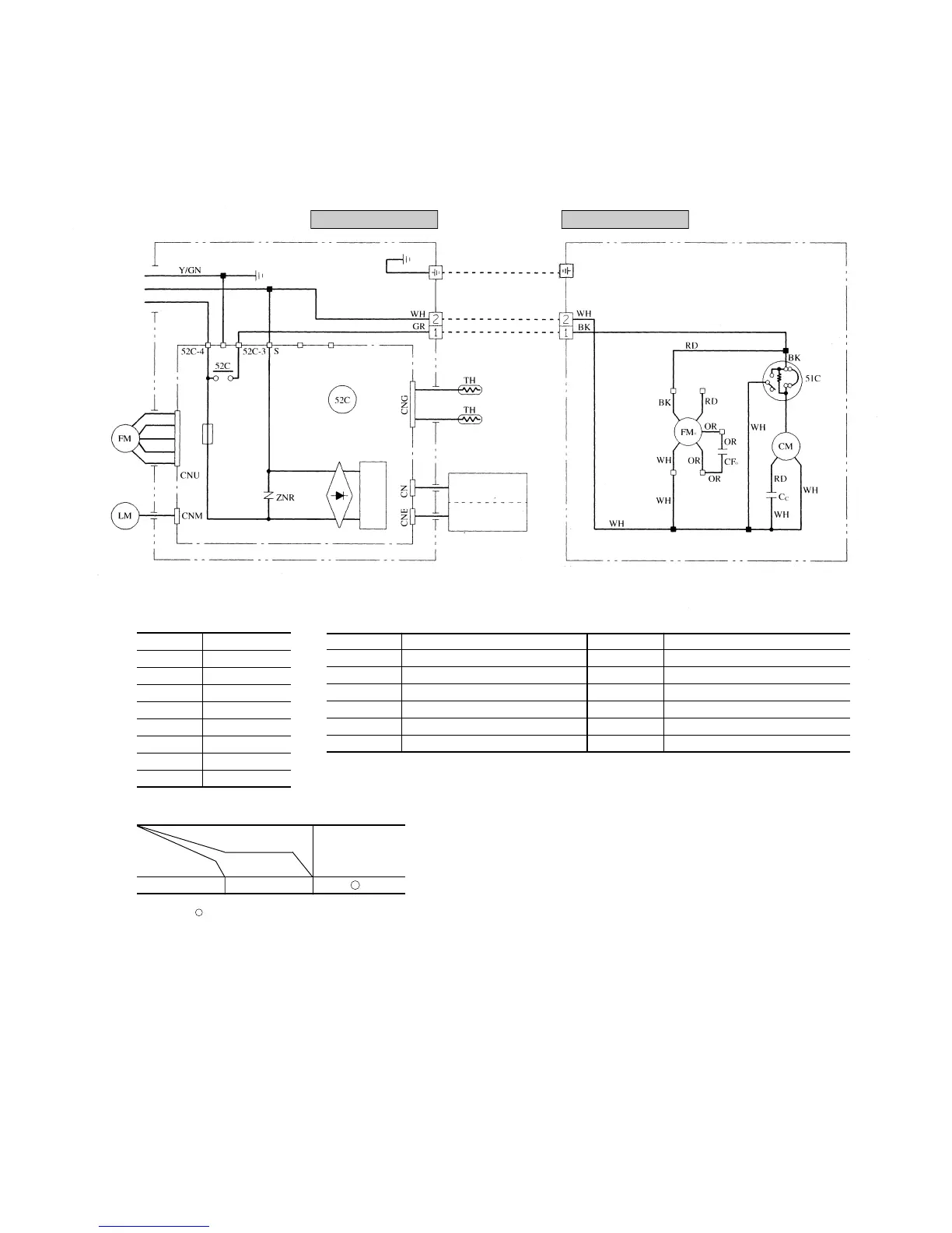
Models SRK501CENF-L, 561CENF-L
Notes (1) : denotes magentized relay ×: denotes demagnetized relay
(2) Th
1
is room temperature thermistor. Th
2
(the heat exchanger thermistor) is frost prevention thermistor.
Power source
1 Phase 220/240V 50Hz
Printed circuit board
Wireless
R-Amp
Display
BL
Y
WH
BK
RD
LB
BR
G
H
F
250V
3.15A
1
2
3
4
5
( )
Indoor unit Outdoor unit
Meaning of marks
Symbol Parts name Symbol Parts name
C
C
Capacitor for CM LM Louver motor
CF
O
Capacitor for FM
O
Th
1
,
2
Thermistor
CM Compressor motor ZNR Varistor
F Fuse 51C Motor protector for CM
FM
I
Fan motor (Indoor unit) 52C Magnetic contactor for CM
FM
O
Fan motor (Outdoor unit)
Table of relay operations
Operation
Cooling
Relay symbol Control part
52C CM
I
1
2
Color symbol
BK Black
BL Blue
BR Brown
RD Red
OR Orange
WH White
Y Yellow
LB Light blue
Y/GN Yellow/Green

Questions and Answers:

Question and Answer IconNeed help?

Do you have a question about the Mitsubishi SRC561HENF-L and is the answer not in the manual?

Mitsubishi SRC561HENF-L Specifications

General IconGeneral
BrandMitsubishi
ModelSRC561HENF-L
CategoryAir Conditioner
LanguageEnglish

Related product manuals