3. HYDRAULIC SYSTEM PREPARATION
To prolong servovalve operational life and to reduce hydraulic system
maintenance, it is recommended that the hydraulic fluid be kept at a cleanliness
level of ISO DIS 4406 Code 16/13 maximum, 14/11 recommended.The most
effective filtration scheme incorporates the use of a kidney loop or “off-line”
filtration as one of the major filtration components.The filter for the “off-line”
filtration scheme should be a B
3
≥75 filter for maximum effectiveness.
Upon system startup and prior to mounting the servovalve, the entire
hydraulic system should be purged of built-in contaminating particles by an
adequate flushing.The servovalve should be replaced by a flushing manifold and
the hydraulic circuit powered up under conditions of fluid temperature and fluid
velocity, reasonably simulating normal operating conditions. New system filters
are installed during the flushing process whenever the pressure drop across the
filter element becomes excessive.The flushing processes should turn over the
fluid in the reservoir between fifty to one hundred times.
To maintain a clean hydraulic system, the filters must be replaced on a
periodic basis. It is best to monitor the pressure drop across the filter assembly
and replace the filter element when the pressure drop becomes excessive. In
addition to other filters that are installed in the hydraulic circuit, it is
recommended that a large capacity, low pressure ß
3
≥75 filter be installed in the
return line. This filter will increase the interval between filter element
replacement and greatly reduce the system contamination level.
4. INSTALLATION
The Moog G761 Series Industrial Servovalve may be mounted in any
position, provided the servovalve pressure, piston and return ports match
respective manifold ports.
The mounting pattern and port location of the servovalve is shown on
Figure 4.The servo-valve should be mounted with 5/16-18 x 1.75 inch long,
socket head cap screws.Apply a light film of oil to the screw threads and torque
to 96 inch pounds.
Wire mating connector for desired coil configuration and polarity. Thread
connector to valve.
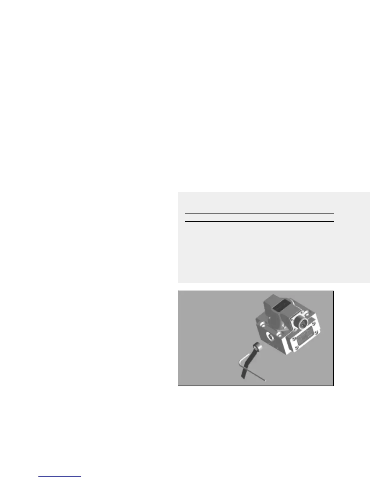
5. MECHANICAL NULL ADJUSTMENT
It is often desirable to adjust the flow null of a servovalve independent of
other system parameters.The “mechanical null adjustment” on the Moog G761
Series servovalve allows at least ±20% adjustment of flow null.
The “mechanical null adjustor” is an eccentric bushing retainer pin located
above the “return” port designation on the valve body (see Figure 2) which,
when rotated, provides control of the bushing position. Mechanical feedback
elements position the spool relative to the valve body for a given input signal.
Therefore, a movement of the bushing relative to the body changes the flow null.
Adjustment Procedure
a. Using a
3
/
32
inch Allen wrench, rotate mechanical null adjustor pin to obtain
desired flow null. If excessive torque (more than 12 in.-lb.) is required to rotate
null adjustor pin, perform Step b.
Note:
Clockwise rotation of null adjustor pin produces open loop flow from port B to port A.
b. Using a
3
/
8
inch offset box wrench, loosen self-locking fitting. DO NOT
remove self-locking fitting. Insert a
3
/
32
inch Allen wrench in null adjustor pin.
Using the
3
/
8
inch offset box wrench to tighten self-locking fitting until a torque
of 10 to 12 in.-lb. is required to rotate null adjustor pin with the Allen wrench.
Perform Step a to establish desired flow null.
Tools and Equipment
a. Allen wrench set (
3
/
32
inch)
b. Torque wrench (10-12 inch-pounds)
c.
3
/
8
inch offset box wrench
6.GENERAL SERVICING RECOMMENDATIONS
a. Disconnect the electrical lead to the servovalve.
b. Relieve the hydraulic system of residual pressure.
c. Remove the servovalve.
Table 1. Replacement Parts
Part Description Qty. Part Number
G761 Series Filter Replacement Kit 1 B52555RK201K1
Filter Plug - Body O-Ring (1) 2 42082-60
End Cap - body O-Ring (1) 2 42082-42
End Cap - Body O-ring (1) 2 42082-1
Filter Disc (1) 1 A67999-65
Base O-Rings 4 42082-22
1 42082-13
(1) Included in Filter Replacement Kit
Figure 2
Mechanical Null Adjustment
 Loading...


