Recommended Test Equipment Section 1: 3-3
6881091C63-F
* Included with ChipMaster packages.
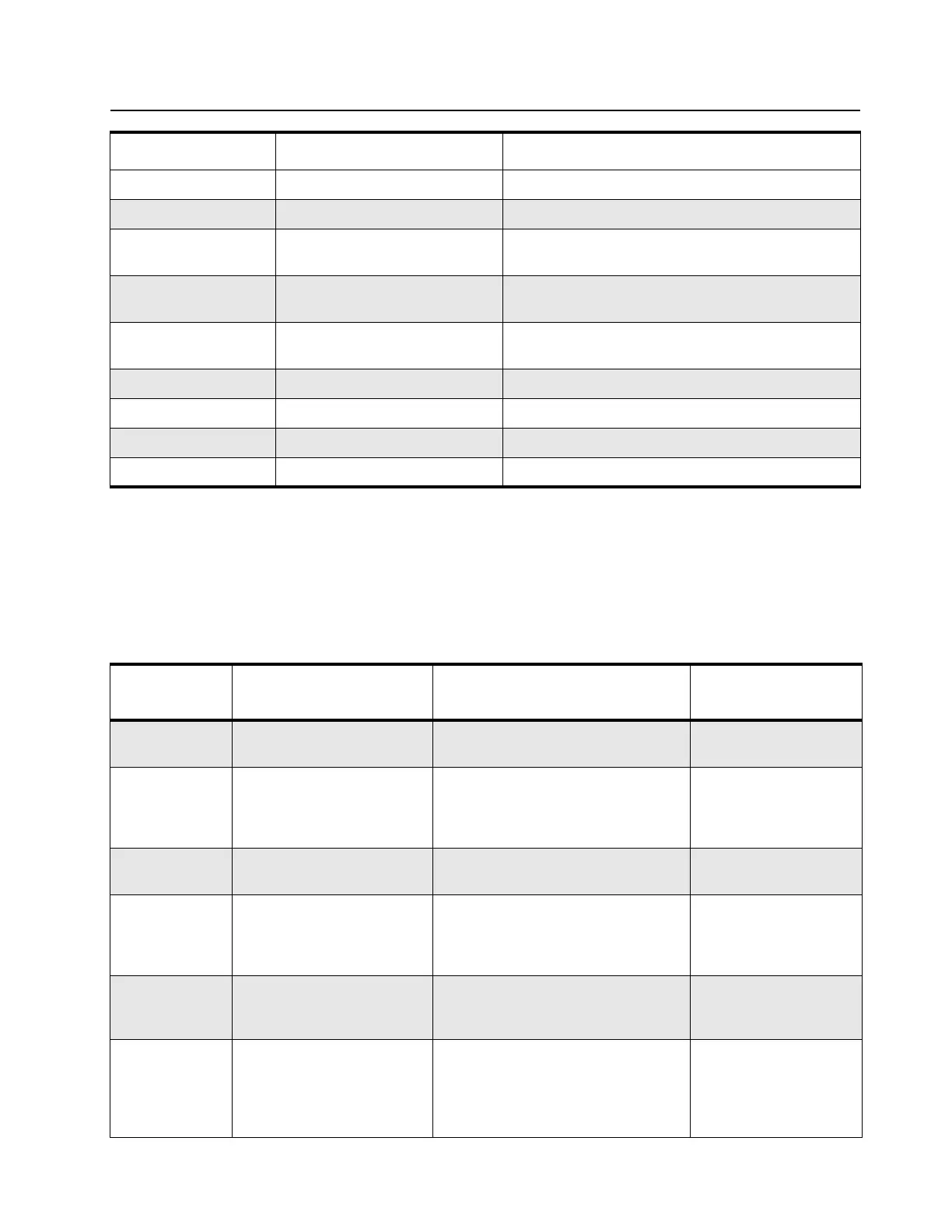
2.0 Recommended Test Equipment
Table 3-2 lists test equipment required to service the mobile radios described in this manual as well
as other two-way radios.
Table 3-2 Recommended Test Equipment
R1427_ Board preheater Reduces heatsink on multi-level boards
R1453_ Digital readout solder station Digitally controlled soldering iron
RLN4008_ Radio Interface Box Enables communications between radio and
computer’s serial communications adapter
RLN4062_ Hot air workstation, 120 V Tool for hot air soldering/desoldering of surface-
mounted integrated circuits
RLN4460_ Portable Test Set Enables connection to audio/accessory jack. Allows
switching for radio testing.
RLN4853_ 10 to 20 Pin Adapter Connects RKN4081_ to the radio accessory connector
RSX4043_ TORX screwdriver Tighten and remove chassis screws
6680387A72 T-8 TORX bit Removable TORX screwdriver bit
6680387A76 T-20 TORX bit Removable TORX screwdriver bit
Motorola Part
Number
Description Characteristics Application
*R1013_ or
*R1370_
SINAD meter or
SINAD meter with RMS
Without RMS audio voltmeter or
with RMS audio voltmeter
Receiver sensitivity
measurements
*R1074_ Fluke 87 digital multimeter True RMS metering, 200 kHz
frequency counter, 32-segment bar
graph with backlit display
Digital voltmeter is
recommended for AC/
DC voltage and current
measurements
*R1377_ AC voltmeter 100 µV – 300 V, 5 Hz – 1 MHz,
10 MΩ input impedance
Audio voltage
measurements
R1439_ or
R1440_
(See Table 3-3)
BIRD wattmeter Power range: 100 mW – 100 W,
2 MHz – 1 GHz, UHF-F connector
Power range: 100 mW – 100 W,
2 MHz – 1 GHz, N-female connector
Transmitter power
output measurements
R1611_ Dual channel 100MHz
oscilloscope (Agilent)
Two-channel, 100 MHz bandwidth,
200 M sample rate/sec, 2 Mb memory/
channel
Waveform
measurements
R2600_NT Comms System Analyzer
(non MPT)
This monitor will substitute for items
with an asterisk*
Frequency/deviation
meter and signal
generator for wide-range
troubleshooting and
alignment
Motorola Part No. Description Application

 Loading...