Installation Method
Page 6mrcool.com
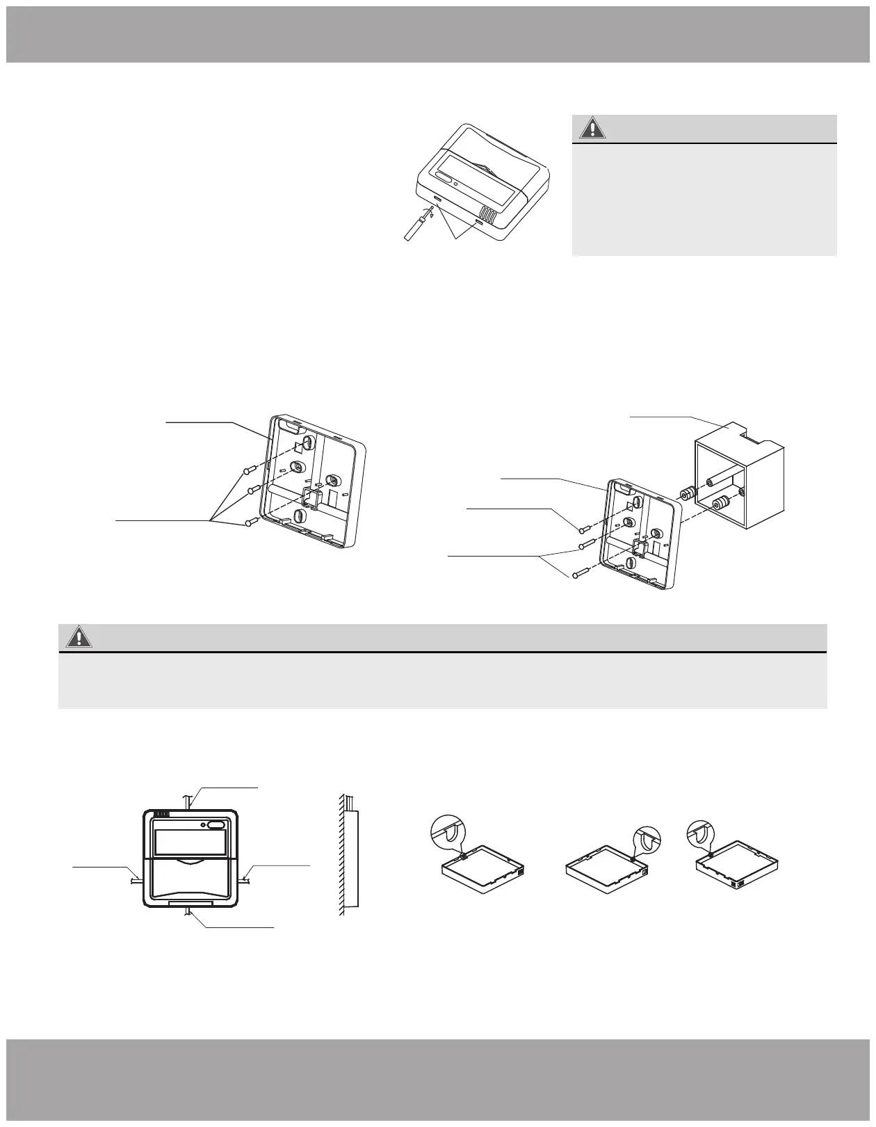
4. Remove Upper Part of Wire Controller
5. Fasten The Back Plate of the Wire Controller
6. Wiring
Fig 2-4
Fig 2-5
• Insert a slot screw driver into the slots in
the lower part of the wire controller (2
places), and remove the upper part of the
wire controller. (Fig.2-4)
Slots
WARNING
The PCB is mounted in the upper
part of the wire controller. Be
careful not to damage the board
with the slot screwdriver.
Back plate
Screws (M4×20)
• For exposed mounting, fasten the back plate on
the wall with the 3 screws (M4×20) and plugs.
(Fig.2-5)
• For flush-mounting, fasten the back plate on the
switch box with 2 screws (M4×25) and fasten it on
the wall with 1 screw (M4×20). (Fig.2-6)
Fig 2-6
Fig 2-7
Switch box
Back plate
Screw (M4×20)
Screws (M4×25)
WARNING
Put on a flat surface. Be careful not to distort the back plate of the wire controller by overtightening the
mounting screws.
Top side
wire outlet
Left side
wire outlet
Right side
wire outlet
Bottom side
wire outlet
Cut location of top
side wire outlet
Cut location of left
side wire outlet
Cut location of right
side wire outlet
Exposed Mounting
There are four outletting positions,
however, only three need cutting.
 Loading...