2-15
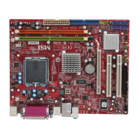
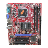
Hardware Setup
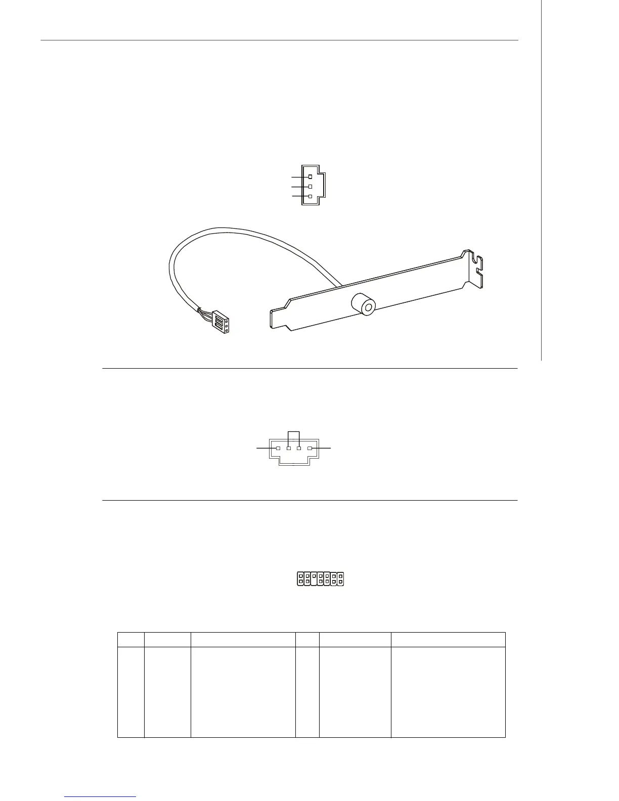
S/PDIF Bracket (Optional)
S/PDIF-Out Connector: JSP1
This connector is used to connect S/PDIF (Sony & Philips Digital Interconnect Format)
interface for digital audio transmission.
CD-In Connector: CD_IN1
This connector is provided for external audio input.
TPM Module connector: JTPM1(optional)
This connector connects to a TPM (Trusted Platform Module) module (optional)
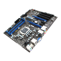
Pin Signal Description Pin Signal Description
1 LCLK LPC clock 2 3V dual/3V_STB 3V dual or 3V standby power
3 LRST# LPC reset 4 VCC3 3.3V power
5 LAD0 LPC address & data pin0 6 SIRQ Serial IRQ
7 LAD1 LPC address & data pin1 8 VCC5 5V power
9 LAD2 LPC address & data pin2 10 KEY No pin
11 LAD3 LPC address & data pin3 12 GND Ground
13 LFRAME# LPC Frame 14 GND Ground
VCC
SPDIF
GND
CD_IN1
GND
R
L
2
1
14
13
JTPM1
 Loading...