2-13
Hardware Setup
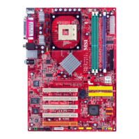
Fan Power Connector: CPUFA1
The CPUFA1 (processor fan) supports system cooling fan with +12V. It sup-
ports three-pin head connector. When connecting the wire to the connectors, al-
ways take note that the red wire is the positive and should be con-
nected to the +12V, the black wire is Ground and should be con-
nected to GND. If the mainboard has a System Hardware Monitor
chipset onboard, you must use a specially designed fan with speed
sensor to take advantage of the CPU fan control.
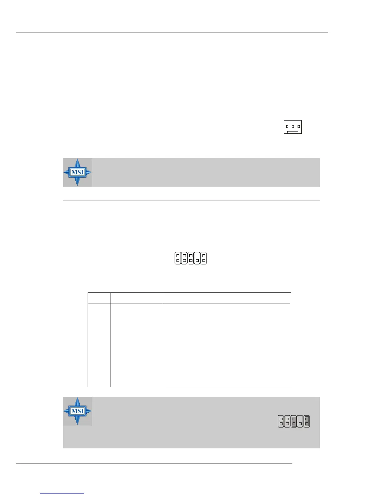
Front Panel Audio Connector: JAUD1
The JAUD1 front panel audio connector allows you to connect to the front
panel audio and is compliant with Intel
®
Front Panel I/O Connectivity Design Guide.
MSI Reminds You...
Always consult the vendors for proper CPU cooling fans.
MSI Reminds You...
If you don’t want to connect to the front audio header, pins
5 & 6, 9 & 10 have to be jumpered in order to have signal
output directed to the rear audio ports. Otherwise, the
Line-Out connector on the back panel will not function.
5
6
10
9
JAUD1
1
2
9
10
PIN SIGNAL DESCRIPTION
1 AUD_MIC Front panel microphone input signal
2 AUD_GND Ground used by analog audio circuits
3 AUD_MIC_BIAS Microphone power
4 AUD_VCC Filtered +5V used by analog audio circuits
5 AUD_FPOUT_R Right channel audio signal to front panel
6 AUD_RET_R Right channel audio signal return from front panel
7 HP_ON Reserved for future use to control headphone amplifier
8 KEY No pin
9 AUD_FPOUT_L Left channel audio signal to front panel
10 AUD_RET_L Left channel audio signal return from front panel
JAUD1 Pin Definition
CPUFA1
Sensor
+12V
GND
 Loading...