Home
MTD
Tractor
700 Series
MTD 700 Series User Manual
4
of 1
of 1 rating
36 pages
Give review
Manual
Specs
To Next Page
To Next Page
To Previous Page
To Previous Page
Loading...
Dimension
“B”
should
be
approximately
1/8"
less
than
Dimension
“A.”
See
figure
15.
A.
)
To
increase
Dimension
“B,”
screw
tie
rod
into
tie
rod
end.
B.
)
To
decrease
Dimension
“B,”
unscrew
tie
rod
from
tie
rod
end.
C.)
Reassemble
tie
rod.
Check
dimensions.
Readjust
if
necessary.
FIGURE
15.
TOE-IN
DIAGRAM
CARBURETOR
ADJUSTMENT
WARNING
If
any
adjustments
are
made
to
the
engine
while
the
engine
is
running
(e.g.
carburetor),
disengage
all
clutches,
and
blades.
Keep
clear
of
all
moving
parts.
Be
careful
of
heated
surfaces
and
muffler.
Minor
carburetor
adjustment
may
be
required
to
com¬
pensate
for
differences
in
fuel,
temperature,
altitude
and
load.
To
adjust
the
carburetor,
refer
to
the
separate
engine
manual
packed
with
your
unit.
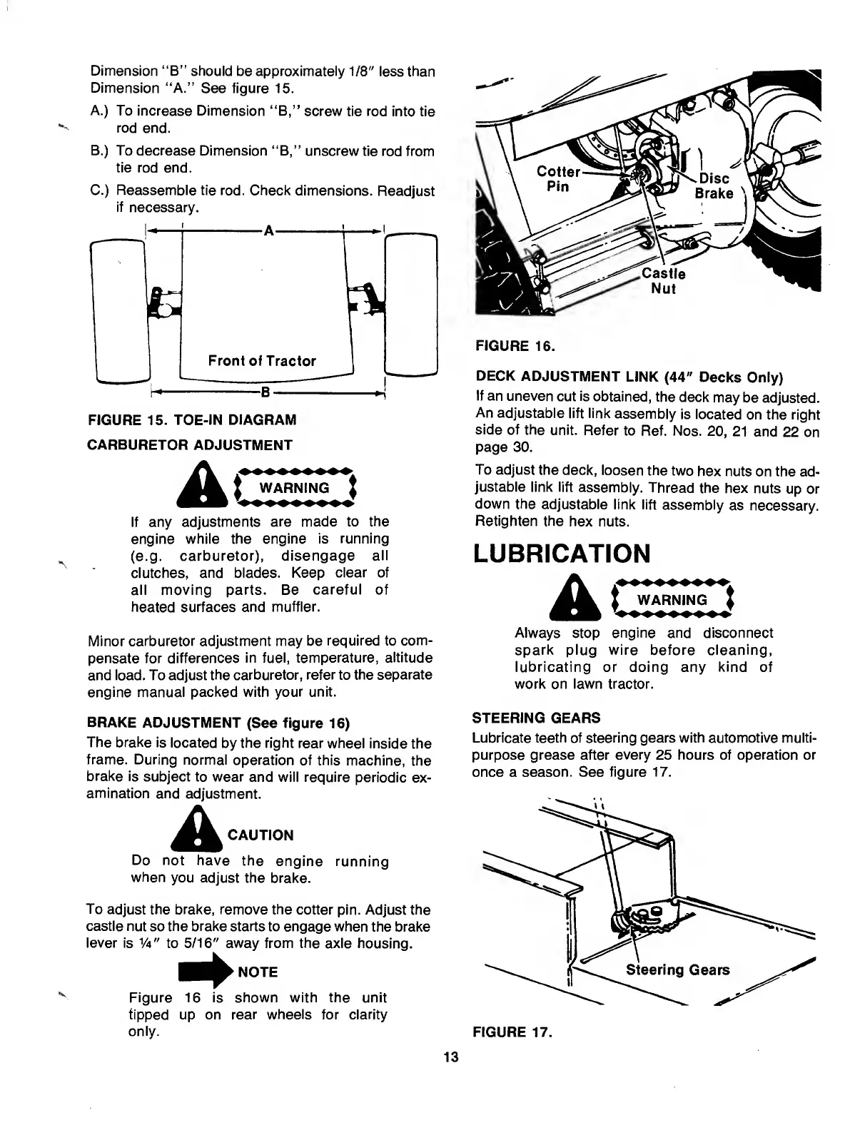
FIGURE
16.
DECK
ADJUSTMENT
LINK
(44"
Decks
Only)
If
an
uneven
cut
is
obtained,
the
deck
may
be
adjusted.
An
adjustable
lift
link
assembly
is
located
on
the
right
side
of
the
unit.
Refer
to
Ref.
Nos.
20,
21
and
22
on
page
30.
To
adjust
the
deck,
loosen
the
two
hex
nuts
on
the
ad¬
justable
link
lift
assembly.
Thread
the
hex
nuts
up
or
down
the
adjustable
link
lift
assembly
as
necessary.
Retighten
the
hex
nuts.
LUBRICATION
WARNING
)
Always
stop
engine
and
disconnect
spark
plug
wire
before
cleaning,
lubricating
or
doing
any
kind
of
work
on
lawn
tractor.
BRAKE
ADJUSTMENT
(See
figure
16)
The
brake
is
located
by
the
right
rear
wheel
inside
the
frame.
During
normal
operation
of
this
machine,
the
brake
is
subject
to
wear
and
will
require
periodic
ex¬
amination
and
adjustment.
A
CAUTiON
Do
not
have
the
engine
running
when
you
adjust
the
brake.
To
adjust
the
brake,
remove
the
cotter
pin.
Adjust
the
castle
nut
so
the
brake
starts
to
engage
when
the
brake
lever
is
Va"
to
5/16"
away
from
the
axle
housing.
Figure
16
is
shown
with
the
unit
tipped
up
on
rear
wheels
for
clarity
only.
STEERING
GEARS
Lubricate
teeth
of
steering
gears
with
automotive
multi¬
purpose
grease
after
every
25
hours
of
operation
or
once
a
season.
See
figure
17.
12
14
Table of Contents
Limited Warranty
2
Steering Wheel Installation
4
Seat Installation
5
Battery Information
6
Activating the Battery
6
Installing the Battery
6
Operation
9
Stopping the Engine
10
Neutral Adjustment
12
Wheel Adjustment
12
Carburetor Adjustment
13
Maintenance
14
Fuel Filter
15
Belt Removal and Replacement
15
Jump Starting
16
Battery Maintenance
16
Battery Storage
16
Off-Season Storage
17
Parts Information
36
Other manuals for MTD 700 Series
Professional Shop Manual
186 pages
Original Operating Instructions
19 pages
Shop Manual
150 pages
Operator's Manual
44 pages
4
Based on 1 rating
Ask a question
Give review
Questions and Answers:
Need help?
Do you have a question about the MTD 700 Series and is the answer not in the manual?
Ask a question
MTD 700 Series Specifications
General
Turning Radius
18 inches
Engine Type
Single-cylinder
Drive Type
Rear-wheel drive
Tire Size (Front)
15x6.00-6
Tire Size (Rear)
20x10.00-8
Related product manuals
MTD 142-760
30 pages
MTD 710, 700
72 pages
MTD 136-700-000
36 pages
MTD Cub Cadet Ultima ZTX4 60
80 pages
MTD Cub Cadet Ultima ZTX5 60
80 pages
MTD Cub Cadet Ultima ZTX5 54
80 pages
MTD Cub Cadet Ultima ZTX4 54
80 pages
MTD Cub Cadet Ultima ZTX6 60
80 pages
MTD Zero-Turn
44 pages
MTD 145-660A
34 pages
MTD 680
32 pages
MTD Cub Cadet Ultima ZTX4 48
80 pages
 Loading...