Home
MTD
Tractor
700 Series
MTD 700 Series User Manual
4
of 1
of 1 rating
36 pages
Give review
Manual
Specs
To Next Page
To Next Page
To Previous Page
To Previous Page
Loading...
When
replacing
the
blade,
be
sure
to
install
the
blade
with
the
side
of
the
blade
marked
“Bottom”
(or
with
part
number)
facing
the
ground
when
the
mower
is
in
the
operating
position.
Make
certain
key
is
in
place
on
the
blade
spindles.
Blade
Mounting
Torque
3/8"
Dia.
Bolt
375
in.
lb.
min.,
450
in.
lb.
max.
5/16"
Dia.
Bolt
150
in.
lb.
min.,
250
in.
lb.
max.
To
insure
safe
operation
of
your
unit,
ALL
nuts
and
bolts
must
be
checked
periodically
for
correct
tightness.
Blade
Spindle
Nuts
If
disassembled
for
any
reason,
tighten
the
blade
spin¬
dle
nuts
for
the
22"
blades
to
between
80
and
100
foot
pounds.
Tighten
the
blade
spindle
nut
for
the
smaller
center
blade
to
between
40
and
45
foot
pounds.
FUEL
FILTER
Your
unit
is
equipped
with
a
replaceable
in-line
fuel
filter.
Replace
filter
whenever
contamination
or
discoloration
is
noticed.
Order
replacement
filter
through
your
engine
authorized
service
dealer.
BELT
REMOVAL
AND
REPLACEMENT
▲
c
WARNING
Disconnect
the
spark
plug
wire
and
ground
it
against
the
engine.
Block
the
wheels
of
the
unit.
NOTE
Figures
19
through
21
are
shown
with
the
unit
tipped
up
for
clarity.
It
is
not
necessary
to
tip
the
unit
to
remove
the
belts.
Rear
Drive
Belt
1.
Remove
the
two
truss
head
screws
which
secure
the
transmission
cover.
2.
Lift
the
transmission
cover.
Unplug
the
green
safe¬
ty
wire
from
beneath
the
transmission
cover.
Remove
transmission
cover.
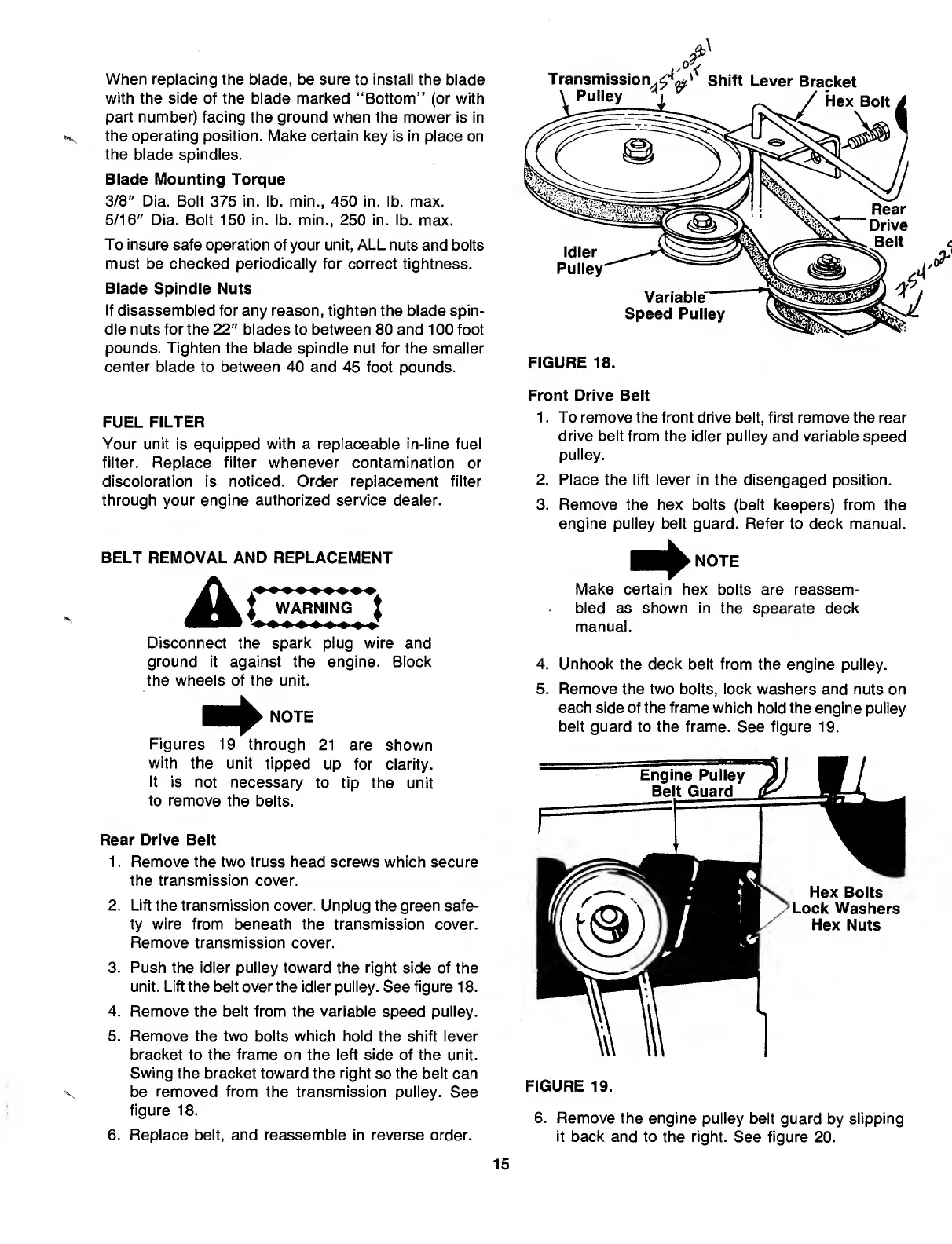
3.
Push
the
idler
pulley
toward
the
right
side
of
the
unit.
Lift
the
belt
over
the
idler
pulley.
See
figure
18.
4.
Remove
the
belt
from
the
variable
speed
pulley.
5.
Remove
the
two
bolts
whicli
hold
the
shift
lever
bracket
to
the
frame
on
the
left
side
of
the
unit.
Swing
the
bracket
toward
the
right
so
the
belt
can
V
be
removed
from
the
transmission
pulley.
See
figure
18.
6.
Replace
belt,
and
reassemble
in
reverse
order.
FIGURE
18.
Front
Drive
Belt
1.
To
remove
the
front
drive
belt,
first
remove
the
rear
drive
belt
from
the
idler
pulley
and
variable
speed
pulley.
2.
Place
the
lift
lever
in
the
disengaged
position.
3.
Remove
the
hex
bolts
(belt
keepers)
from
the
engine
pulley
belt
guard.
Refer
to
deck
manual.
Make
certain
hex
bolts
are
reassem¬
bled
as
shown
in
the
spearate
deck
manual.
4.
Unhook
the
deck
belt
from
the
engine
pulley.
5.
Remove
the
two
bolts,
lock
washers
and
nuts
on
each
side
of
the
frame
which
hold
the
engine
pulley
belt
guard
to
the
frame.
See
figure
19.
FIGURE
19.
6.
R
emove
the
engine
pulley
belt
guard
by
slipping
it
back
and
to
the
right.
See
figure
20.
15
14
16
Table of Contents
Limited Warranty
2
Steering Wheel Installation
4
Seat Installation
5
Battery Information
6
Activating the Battery
6
Installing the Battery
6
Operation
9
Stopping the Engine
10
Neutral Adjustment
12
Wheel Adjustment
12
Carburetor Adjustment
13
Maintenance
14
Fuel Filter
15
Belt Removal and Replacement
15
Jump Starting
16
Battery Maintenance
16
Battery Storage
16
Off-Season Storage
17
Parts Information
36
Other manuals for MTD 700 Series
Professional Shop Manual
186 pages
Original Operating Instructions
19 pages
Shop Manual
150 pages
Operator's Manual
44 pages
4
Based on 1 rating
Ask a question
Give review
Questions and Answers:
Need help?
Do you have a question about the MTD 700 Series and is the answer not in the manual?
Ask a question
MTD 700 Series Specifications
General
Turning Radius
18 inches
Engine Type
Single-cylinder
Drive Type
Rear-wheel drive
Tire Size (Front)
15x6.00-6
Tire Size (Rear)
20x10.00-8
Related product manuals
MTD 142-760
30 pages
MTD 710, 700
72 pages
MTD 136-700-000
36 pages
MTD Cub Cadet Ultima ZTX4 60
80 pages
MTD Cub Cadet Ultima ZTX5 60
80 pages
MTD Cub Cadet Ultima ZTX5 54
80 pages
MTD Cub Cadet Ultima ZTX4 54
80 pages
MTD Cub Cadet Ultima ZTX6 60
80 pages
MTD Zero-Turn
44 pages
MTD 145-660A
34 pages
MTD 680
32 pages
MTD Cub Cadet Ultima ZTX4 48
80 pages
 Loading...