Read complete instructions prior to installation
and operation of the unit.
WARNING : Risk of electric shock.
SAFETY PRECAUTION
!
All safety related codifications, symbols and instructions that
appear in this operating manual or on the equipment must be
strictly followed to ensure the safety of the operating personnel
as well as the instrument.
If all the equipment is not handled in a manner specified by
the manufacturer, it might impair the protection provided by the
equipment.
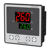
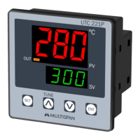
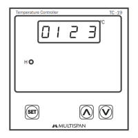
UTC-121P
INPUT SPECIFICATION:
Input Types
PV = Process Value
SV = Set Value
Resolution
Indication
Accuracy
Input Range
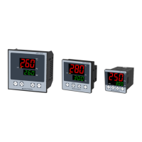
TEMPERATURE CONTROLLER
0 to 600°C,
0 to 1200°C,
-99 to 400°C,
-99.9 to 400.0°C,
J
K
PT-100
PT.1
J,K,PT-100 = 1°C
±1% of FSD ± 1°C
PT.1 = 0.1°C
DISPLAY AND KEYS:
CONTROL METHOD:
DIMENSION:
OUTPUT SPECIFICATION:
POWER SUPPLY:
ENVIRONMENT CONDITION:
Display
Heating
Size
Keys
Cooling
Panel Cutout
Power
Consuption
(VA Rating)
Relative Humidity
Protection Level
(As per request)
Relay
Output Signal
Supply
Voltage
Operating Temp.
Relay Type
Rating
Upper: 4 digit, 7 segment, 0.70” Red
1) PID control with Auto-Tuning
Lower: 4 digit, 7 segment, 0.50” Green
2) ON-OFF control
96 (H) x 96 (W) x 52 (D) mm
100 to 270V AC, 50-60Hz
1 - Control output indication
2 - Auto tuning “ON” indication
3 - Blinking DP Will Indicate Delay time Count
0°C to 55°C
UP to 95% RH
(non-condensing)
IP-65 (Front side) As per IS/IEC
60529 : 2001
1 Nos
12V DC, 30mA DC
(On-Off condition)
Relay parallel to SSR
1C/O (NO-C-NC)
10A, 230V AC / 28V DC
SET, INC, DEC, ENT
ON-OFF control
92 (H) x 92 (W) mm
4VA @ 230V AC MAX
Relay Output
SSR Drive Output
TECHNICAL SPECIFICATION
STATUS LED DESCRIPTION
KEY OPERATION
MECHANICAL INSTALLATION
TERMINAL CONNECTION
To enter in parameter setting
For start/stop PID auto tuning
Press
6 sec
Press 3 sec
+
To go in factory setting mode
PRESS KEYFUNCTION
OPERATOR MODE
PARAMETER SETTING MODE
To set parameter value
To increment parameter value.
To decrement parameter value.
Set parameter to be save & exit.
WARNING GUIDELINES
WARNING : Risk of electric shock.
1. To prevent the risk of electric shock, power supply to the
equipment must be kept OFF while doing the wiring
arrangement. Do not touch the terminals while power is
being supplied.
2. To reduce electro magnetic interference, use wire with
adequate rating and twists of the same of equal size shall
be made with shortest connection.
3. Cable used for connection to power source, must have a
cross section of 1mm or greater. These wires should have
insulations capacity made of at least 1.5kV.
4. When extending the thermocouple lead wires, always use
thermocouple compensation wires for wiring for the RTD
type, use a wiring material with a small lead resistance
(5 max per line) and no resistance differentials among
three wires should be present.
5. A better anti-noise effect can be expected by using
standard power supply cable for the instrument.
Ω
INSTALLATION GUIDELINES
1. This equipment, being built-in-type, normally becomes a
part of main control panel and in such case the terminals
do not remain accessible to the end user after installation
and internal wiring.
2. Do not allow pieces of metal, wire clippings, or fine metallic
fillings from installation to enter the product or else it may
lead to a safety hazard that may in turn endanger life or
cause electrical shock to the operator.
3. Circuit breaker or mains switch must be installed between
power source and supply terminal to facilitate power ‘ON’
or ‘OFF’ function. However this mains switch or circuit
breaker must be installed at convenient place normally
accessible to the operator.
4. Use and store the instrument within the specified ambient
temperature and humidity ranges as mentioned in this
manual.
MECHANICAL INSTALLATION GUIDELINES
1. Prepare the panel cutout with proper dimensions as shown
above.
2. Fit the unit into the panel with the help of clamp given.
3. The equipment in its installed state must not come in close
proximity to any heating source, caustic vapors, oil steam,
or other unwanted process Byproducts.
4. Use the specified size of crimp terminal (M3.5 screws) to
wire the terminal block. Tightening the screws on the
terminal block using the tightening torque of the range of
1.2 N.m.
5. Do not connect anything to unused terminals.
MAINTENANCE
1. The equipment should be cleaned regularly to avoid blockage
of ventilating parts.
2. Clean the equipment with a clean soft cloth. Do not use
isopropyl alcohol or any other cleaning agent.
3. Fusible resistor must not be replaced by operator.
Page 1
11
13
13
11
11
12
12
12
3-Wire RTD 2-Wire RTD
Thermocouple
Install jumper
when using
2 Wire RTD
Sensor input
+
Sensor Input
96
52
92
92
3
96
Outline Dimension (mm)
Panel Cutout
Dimension (mm)
ENTSET
UTC 121P
TUNE
ºC
PV
SV
32
4
2
3
5
(FSD:-Full Scale Deflection)
1
2
3
2
3
45
2
5
00
1
7
8 9 102 3 4
5
6
NC
C
NO
RELAY
L
N
!
121314 111617181920 15
RTD
TC
+
-
+
-
O/P
S.S.R
~
50/60 Hz
4VA
100
270V AC
Made in India
www.multispanindia.com