NAPCO Gemini C-Series Control Panel Programming Instructions--Volume 1
NAPCO Security Group
Programming Instructions, Volume 1 Page 13
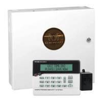
GEMC-FK1 KEYPAD OPERATION
To Access control functions (such as SILENCE, RESET,
ACK. buttons etc.), keypad must be "unlocked" by en-
tering code then pressing ENTER (UNLOCK). Keypad
will remain unlocked until relocked by menu choice or
after approximately 5 minutes of inactivity. Note: If the
feature "Keypad 1 Always Unlocked for User Func-
tions" is enabled, Fire Keypad #1 will remain un-
locked continually. See "Keypad 1 Always Unlocked
for User Functions" and "All Keypads Unlocked for
Silence, Reset and Supp." in the Installation instruc-
tions Fire Glossary.
STANDBY
Keypad displays:
SYSTEM NORMAL
11/01/12 12:05 AM
This is the normal mode. The keypad LCD displays
"SYSTEM NORMAL" above current date and time. Green
AC ON light is lit.
ALARM
Keypad displays:
FIRE Z123 001
XX/XX/XX HH:MM AM
123-SMK NW STAIR
3
RD
FLOOR
LCD displays initial Fire alarm, "FIRE ZXXX" and the
EVENT# on the first line with the date and time of the
alarm on the second line, then scrolls to the description
of the zone in alarm. The FIRE LED flashes and alarm
sounders / indicators are active. Note: The ">" follow-
ing the EVENT# indicates additional information; press
PRIOR or NEXT to view.
SILENCE ALARM
"Unlock" keypad, press ACK and then press SILENCE.
After sounder silences, the SILENCED icon turns on
and FIRE LED changes from flashing to steady.
RESET ALARM
"Unlock" keypad (if not already unlocked), then press
RESET. LCD prompts "ATTEMPTING RESET ...
Please WAIT".
If all Fire devices/zones reset and troubles restore, the
"SYSTEM NORMAL" display will return.
ALARM TEST
LCD must display "SYSTEM NORMAL" before initiating
test. In addition, call central station before initiating
test.
To initiate system test (s):
"Unlock" keypad, press MENU until "DO FIRE DRILL"
displays. Press YES or ENTER. Follow WI instruc-
tions. Note: A Fire Drill Zone must be programmed in
the NAC/Output Assignment screen, NAC/Output Op-
tions tab.
TROUBLE
LCD displays initial trouble "SYStrbl… XXX" (if highest
priority condition) and TROUBLE icon flashes.
Note: The " >" following the EVENT# indicates ad-
ditional information; press PRIOR or NEXT to view.
SILENCE TROUBLE
"Unlock" keypad, then press ACK to silence. Trouble
sounder silences and TROUBLE icon changes from
flashing to steady.
RESET TROUBLE
After all Fire devices reset and all troubles restore, the
"SYSTEM NORMAL" display will return and the TROU-
BLE icon will extinguish.
OFF-NORMAL POSITION OF CIRCUITS
To Disable a Zone / Output Circuit:
"Unlock" keypad, then press MENU until "ZONE DI-
RECTORY / "OUTPUT DIRECTORY" option displays.
Press YES or ENTER. Scroll to desired zone/output
using NEXT and/or PRIOR buttons.
Press SILENCE (DISABLE) button (the DISABLED
icon turns on). Press RESET to exit menu (the TROU-
BLE icon turns on).
RESTORE ZONE / OUTPUT
LCD TROUBLE icon and DISABLED icon are on.
"Unlock" keypad, then press MENU until "ZONE DISA-
BLE / OUTPUT DISABLE" option displays. Press YES
or ENTER. Press NEXT and/or PRIOR until desired
zone/output displays.
Press SILENCE (DISABLE). The DISABLE icon turns
off. Press RESET to exit menu. If all other conditions
are restored, the "SYSTEM NORMAL" display will return.
FUNCTIONS OF DISPLAYS
LCD - Displays initial highest priority condition,
system status, Menu options and details.
SUPV Icon - Flashes in supervisory alarm; steady
when silenced.
TROUBLE Icon - Flashes when Fire system is in
trouble; steady when silenced / acknowledged.
DISABLED Icon - On steady when zones or cir-
BASIC OPERATION (CONT'D)
 Loading...