StarLink
™
SLE-LTE Commercial Series Alarm Communicators -- Installation Instructions 1
armed condition, any loss of communication must be
treated as a Burglary Alarm at the Central Station.
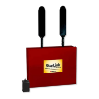
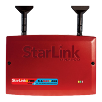
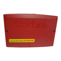
The following models are available:
SLE-LTEV-CFB-PS: Commercial / Residential Fire and
Burglary Radio in red metal housing with SLE-ULPS-R
power supply and 16.5V / 20VA transformer mounted
inside housing
SLE-LTEV-CB-TF: Commercial / Residential Burglary
and Residential Fire Radio in white metal housing with
SLE-ULPS-R power supply and TRF12/T123 plug-in
16.5V / 20VA transformer
SLE-LTEV-CFB: Commercial / Residential Fire and Bur-
glary in red metal housing. Powered directly from control
panel (no power supply, no transformer, rated 12/24VDC
input)
SLE-LTEV-CB: Commercial / Residential Burglary and
Residential Fire Radio in white metal housing. Powered
directly from control panel (no power supply, no trans-
former)
The following features are included with models that include
a SLE-ULPS-R power supply:
Power limited output to the StarLink radio PC board 12V
input terminals
Battery connection red and black flying leads
Monitored battery charging and Active battery test circuits
StarLink radio trouble input (from StarLink radio PC board
PGM1 terminal to detect StarLink radio trouble)
Requires a sealed lead acid min 4AH / max 7AH battery
for minimum 24-hour standby time (max charge current
200mA).
Trouble relay output (C, N/O and N/C terminals) to wire
to a panel zone dedicated to "LTE Trouble" (dry con-
tacts). Remove jumper "J2" to isolate common from
ground
Green AC ON LED visible from the exterior housing
Yellow TROUBLE LED on PC board. Flashes signify:
One flash: AC fail / brownout (2 hour delay)
Two flashes: Low battery
Three flashes: Charging circuit trouble
Four flashes: StarLink radio trouble
The housing-mounted transformer (when provided) is mount-
StarLink™ SLE-LTE Commercial Series
Alarm Communicators
INSTALLATION INSTRUCTIONS
WI2226ALF 8/18
333 Bayview Avenue
Amityville, New York 11701
For Sales and Repairs, (800) 645-9445
For Technical Service, (800) 645-9440 or visit us at
http://tech.napcosecurity.com/
(Note: Technical Service is for security professionals only)
Publicly traded on NASDAQ Symbol: NSSC
© NAPCO 2018
INTRODUCTION
The StarLink
™
Commercial / Residential Fire and Burglary
alarm capture radio communicators are fully supervised,
wireless digital two-way subscriber units supported by an
extensive nationwide wireless network. All models are
compatible with most 12VDC alarm control panels (always
adhere to the documentation provided by the control panel
manufacturer). Model SLE-LTEV-CFB is compatible with
most 12 or 24VDC control panels. All can function as a
backup to existing telephone lines, or as sole path primary
communicators. In backup mode, all units will automatical-
ly switch the communication channel from the telephone
line to the network when telephone line trouble is detected.
See WI2140 for programming information.
The SLE-LTE Series radios use data-capture technology
that captures the alarm report from the control panel and
transmits the alarm signals to the SLE Control Center; the
alarm signals are then forwarded to ANY central station via
Contact ID or Sur-Gard System II or Sur-Gard System V
central station receivers via TCP/IP using standard line
security. The SLE Control Center reports a trouble signal
in the event that the network does not receive the expected
supervision signal from the wireless communicator.
For Commercial Burglary installations, under the
( ( ( ( ( ( ( ( ( ( ) ) ) ) ) ) ) ) ) )
(1)
(2)
Control
Panel
Network
Operator
UL Classified StarLink Network
Operations Center
(3)
CENTRAL
STATION
(5)
(4)
STARLINK RADIO REPORTING PATH
The diagram below shows the transmission path of a
signal from the StarLink radio to the central station.
1. Signal from a Control Panel.
2. StarLink radio receives the signal transmission
(from the TIP an RING wires); sends RF signal
through the network operator.
3. Network Operator, part of the vendor system, a
section of the cellular spectrum.
4. SLE Control Center, receives and routes data.
5. Central Station.
StarLink
Radio
AGENCY LISTINGS
UL 864 Standard For Control Units and Accessories For
Fire Alarm Systems, 10th Edition
UL 1610 Standard For Central-Station Burglar-Alarm Units
UL 985 Standard For Household Fire Warning System Units
UL 1023 Standard For Household Burglar-Alarm System
Units
LTEV models are Verizon
®
Network Certified



 Loading...