2
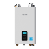
Gas Piping Connections
>
Gas Supply Line
Gas Inlet Adapter
Gas
Regulator
Gas supply
Bottom View
The boiler is
recommended to be
the rst appliance to
be connected to the
gas supply line.
The gas meter capacity
must be greater than
the total gas capacity of
connected appliances.
Example:
Gas meter
425 CFH
≥
Boiler
195 CFH
+
Furnace
58.8 CFH
+
Domestic gas stove
63.7CFH
* 1 CFH=1,020 Btuh
3
/
4
" rigid pipe can be used; refer to the sizing tables in the Installation & Operation
Manual for limitations. Avoid using
3
/
4
" corrugated connectors or tubing as noise may
occur.
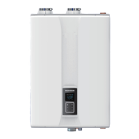
Condensate Drain Connection
>
A condensate drain pipe must be connected to the ¾” condensate outlet tting at the
bottom of the unit and water must be poured into the exhaust connection to ll the
condensate trap.
Condensate trap
Floor drain
Water
The end of the ¾” (NPT) plastic piping should drain into a laundry tub or into a oor
drain.
Note
Do not submerge the end of
the pipe in water.
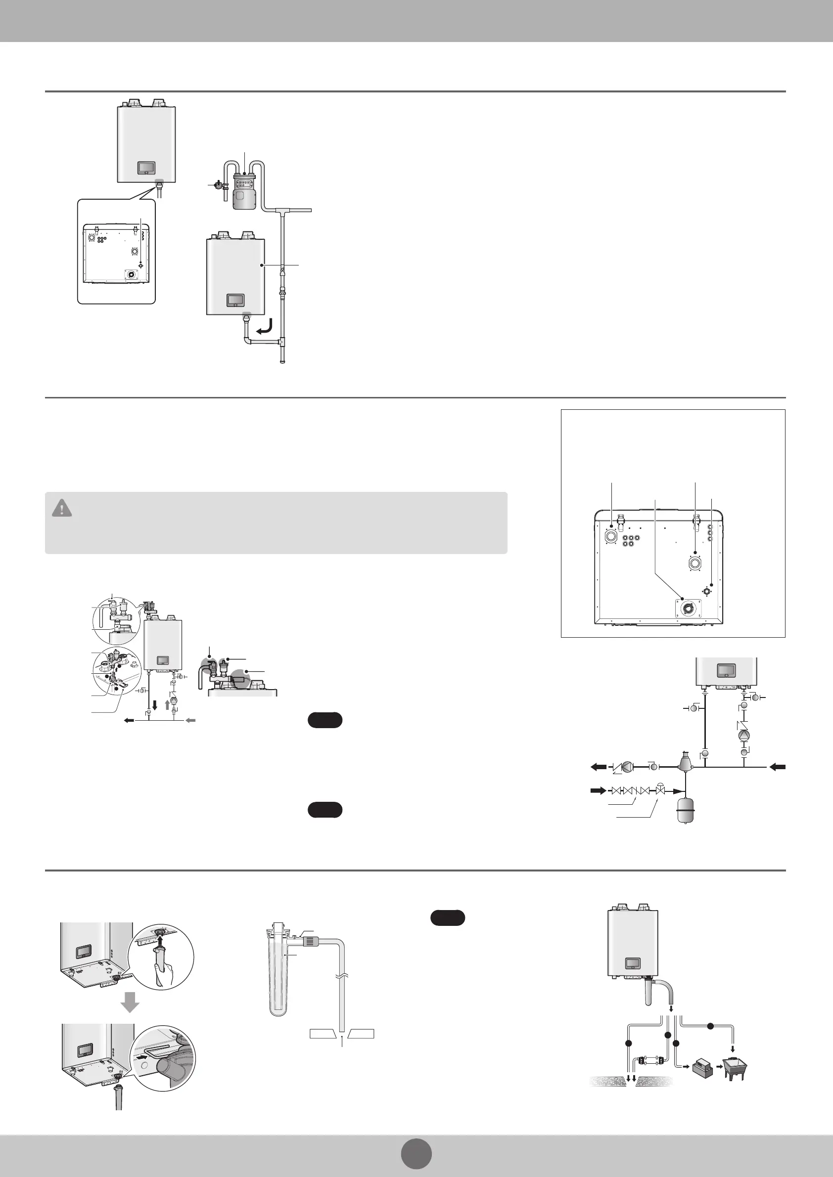
a
b
c
d
Direct to the external drain
To the drain
via a
neutralizer
External drain
To the laundry tub
To the laundry tub
via a condensate pump
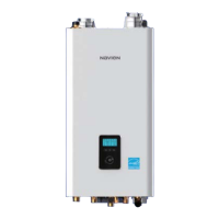
Water Piping Connections
>
Water Piping Connections
Heating
Supply
Condensate
Outlet
Heating
Return
Gas
Connection
From
System
Expansion Tank
Backow Preventer
Pressure Reducing
Valve
Make-up Water
Pump
To System
Air Separator
Pressure Relief Valve
Space Heating System
A pressure relief valve must be installed when installing piping for a heating system.
Install the included
3
/
4
in, maximum 50 psi pressure relief valve on the space heating supply.
An ASME approved HV pressure relief valve for space heating system is supplied with the boiler.
You may install the pressure relief valve on the space heating supply of the Navien Manifold System, or on the top connection along
with the air vent (and an external LWCO, if required).
CAUTION
Do not solder piping directly onto the water connections, as the heat may cause damage to internal components. Use
threaded water connections only.
System Fill Connection
Pressure Relief Valve
Air Vent
PRV-Air Vent
Adapter
Air Vent
Bushing
Air Vent
Bushing
PRV-Air Vent
Connection
Clip
Air Vent
External
LWCO
Pressure
Relief Valve
The Navien NFB boiler comes with an air vent and an
adapter bushing that must be connected to the air vent
connection. The vent eciently removes the air from
the space heating system.
To secure the adapter to the tting, install the provided
clip after inserting the PRV-air vent adapter into the
connection on top of the unit.
When installing the air vent, install the air vent bushing
between the air vent and the top connection.
Before lling the boiler, remove the air vent cap to allow
the system to ll properly. Replace the cap when the
system is full.
Note
Prior to connecting piping to the boiler, ush
the entire system to ensure it is free of
sediment, ux, scale, debris or other
impurities that may be harmful to the system
and boiler. During the assembly of the
heating system, it is important to keep the
inside of the piping free of any debris
including construction dust, copper burr,
sand and dirt.
Note
Ensure that the vent cap is re-installed and
the vent screws on the system and boiler
pumps are properly tightened before testing
or operating the system.
 Loading...