Installation Guide
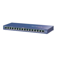
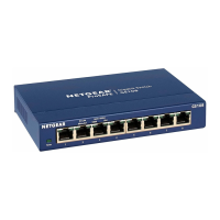
ProSafe™ 16-port Gigabit Switch GS116v2
Estimated Installation Time: 5–10 minutes
Package Contents
When you open the box, verify that you received everything. The package includes:
• ProSafe 16-port Gigabit Switch GS116v2
• AC power adapter
• Wall-mounting kit (2 screws, 2 anchors)
• Installation Guide (this document)
If you do not have everything listed here, see the support information card for
contact information. If you do not have a support information card, get contact
information in the technical support section at www.NETGEAR.com.
Prepare to Install the Switch
Decide where you want to place the switch. Find a flat horizontal surface such as a
table, desk, or shelf. The switch comes with wall-mounting screws. You can use the
screws if you want to hang the switch in an open space on a wall. Make sure the
selected location is:
• Not in direct sunlight or near a heater or heating vent.
• Not cluttered or crowded. There should be at least 2 inches (5 cm) of clear
space on all sides of the switch.
• Well ventilated (especially if it is in a closet).
You need one Category 5e (Cat 5e) Ethernet cable with RJ-45 connectors for each
device you want to connect to the switch. Each Ethernet cable needs to be less than
328 feet (100 meters).
Installation
1. Either place the switch on a flat surface, or wall-mount the switch.
2. To connect the switch, for each device, insert one end of an Ethernet cable into
the port in the device and insert the other end into one of the Ethernet ports on
the switch.
3. Connect the power adapter cord into the back of the switch, and then plug the
adapter into an electrical outlet or power strip.
The Power LED should light up.
4. Check the LEDs to confirm that all connections are correct.
The following table describes LED behavior.
LED Activity
Power • On: The switch has power.
• Off: No power.
RJ-45 ports • Right LED on: 10 Mbps connection to a powered device.
• Left LED on: 100 Mbps connection to a powered device.
• Both LEDs on: 1000 Mbps connection to a powered device.
• Blinking: Activity on this port.
Installation
Wall-Mount the Switch
1. If you are wall-mounting the switch, drill pilot holes for the anchors.
2. Insert the anchors, and then the screws. Tighten the screws, leaving about
4.8 mm of the screw exposed as shown.
3. Slip the case over the screws.
97.0 mm
4.8 mm
GS116 IG.fm Page 1 Wednesday, February 8, 2012 10:07 AM