LP21/LP22
LP21/LP22 Quick start guide 1.1 EN 1|4
Sensors
EN - Quick start guide
NOTE
Read the operating instructions
You can find detailed instructions and comprehensive information in
the full user manual for the product. This document is available on the
www.niceforyou.com.
Read and keep instructions
Read this document before you use the product for the first time, and
keep it in a safe place for future reference.
Maintenance and repairs
No maintenance or servicing are required for this product.
In the event of malfunctions and faults, please contact the vendor or
the manufacturer.
WARNING
Improper use
The device is subject to the manufacturer’s guarantee conditions valid
at the time of purchase. The manufacturer shall not accept any
responsibility for incorrect manual or automatic parameter settings
performed on a device or the inappropriate use of a device.
Improper repairs
Repairs may only be performed by the manufacturer. Failure to comply
results in endangering the safety of the device and renders the
warranty null and void.
Permitted power sources
The power supply must meet the requirements for safety extra-low
voltage (SELV).
Essential safety equipment
The device may not be used as a safety component as defined by the
Machinery Directive 2006/42/EG, the Construction Products
Regulation 305/2011/EU or other safety regulations. Systems posing a
threat of danger require additional safety equipment.
1 Product overview
Product components
LP22/LP21 Traffic Detector
Plug-in terminal blocks (1 x supply, 1 x loop, 2 x relays)
Quick guide
Tab. 1: Scope of delivery
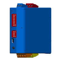
Fig. 1: LP21/LP22 product image
Index
Component
1 Terminal block output 1:
• Relay 1 (yellow)
2 Terminal block loop channel input (orange)
3 Reset button
4 USB interface
5 DIP switch 2 (LP22)
6 LED‘s loop channel 1 (red + blue) LP21
LED‘s loop channel 2 (red + blue) LP22
7 DIP switch 1
8 LED‘s loop channel 1 (red + blue) LP22
9 Terminal block AC/DC (blue)
10 Terminal block output 2:
• Relay 2 (red)
11 Mounting device for DIN rail
Tab. 2: LP21/LP22 component list
Technical data
Dimensions 22.5 x 79.0 x 81.0 mm (W x H x L
without terminals)
Power supply (1x blue)
10 – 30 VDC / 10 – 26 VAC, max. 2
W (SELV)
Protection type IP20
permissible operating
temperature
-37 – +70°C
relative humidity < 95 % (non-condensing)
Loop inputs (1x orange, 2-pole, 4-pole for double channel variants)
• max. inductivity range
20 - 700 µH (see note 1)
• recommended
inductivity range
100 – 300 µH
• operating frequency 30 - 130 kHz
• max. cable length 200 m
• max. internal resistance 20 Ω (including cable)
2 relays
(1x yellow + 1x red)
max. 48 V (AC/DC), 2 A, 60 W,
125 VA (SELV)
min. 1 mA / 5 V
Configuration switch 1
(all variants)
8-pole DIP switch
Configuration switch 2
(2 channel variants)
4-pole DIP switch
LED (1x blue + 1x red per loop channel)
Reset Push button
PC interface USB port, type mini AB
Tab. 3: Technical data