GB
3
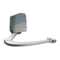
2.5) Assembly of the straight arm (Fig. 7)
Use the M8x55 screw with its relative grower washer. Make sure the arm is positioned by making it come out of the front part.
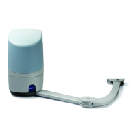
2.6) Mounting the gearmotor (Fig. 8)
Insert the POP in the plate at point C and mount it onto the former using M6x100 screws and the nuts supplied.
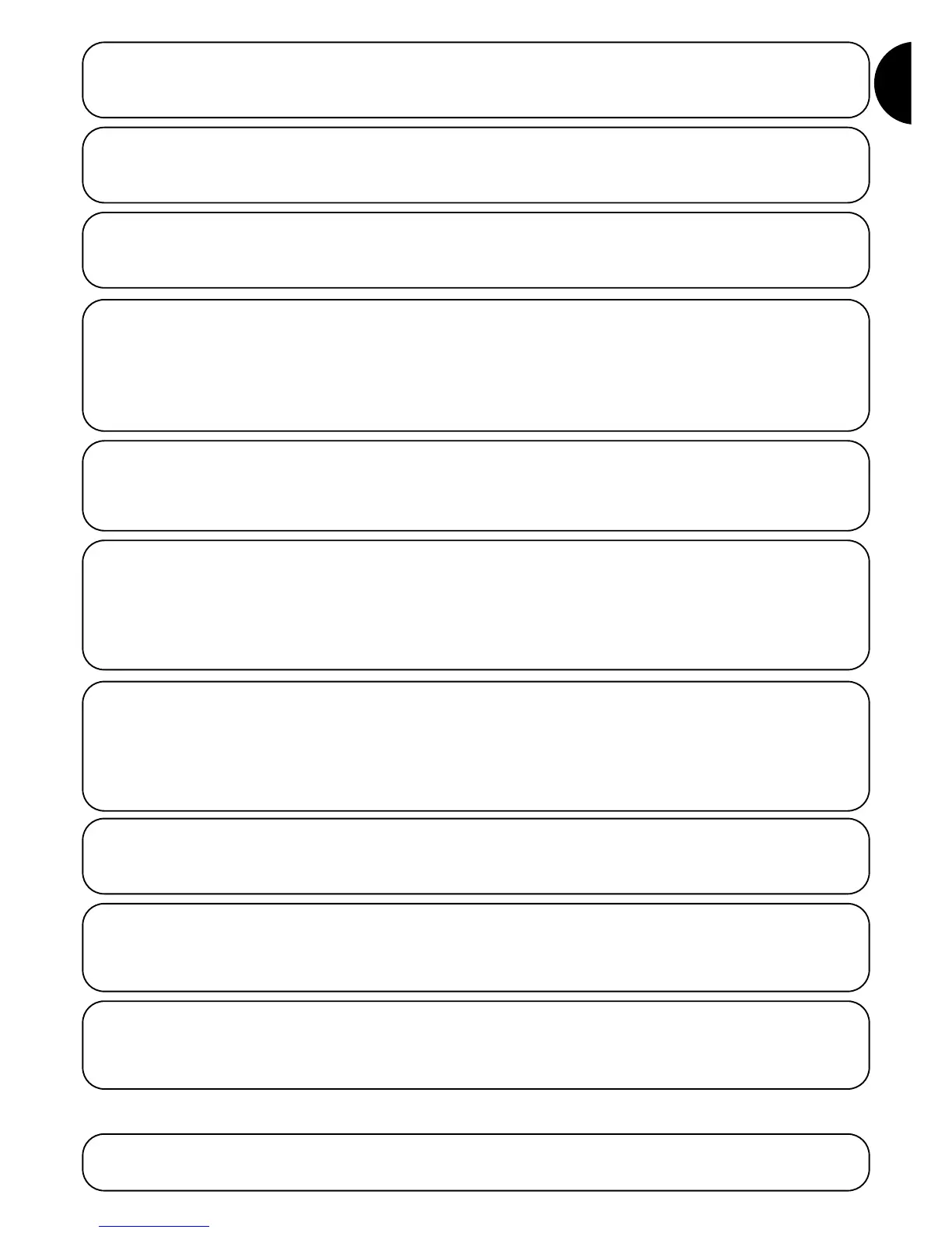
Using the pins supplied, and the corresponding safety rings, fasten
the bent arm to the straight arm, and the leaf mounting bracket to
the bent arm.
Fasten the leaf mounting bracket to the gate as far away as possible
from the post, extending the arms to their maximum reach (Fig. 5).
The bracket can be welded to the gate or fastened with screws suit-
ed to the gate material.
The release system is assembled in six steps:
A:remove the plastic cover (1)
B: screw the pin (3) onto the release shaft (2)
C: screw the cable stretcher (4) into the special hole (5)
D: secure the spring (6) to the pin (3) and to the fastening point visi-
ble in the shell.
E:slide the release cable (7) into the pin hole (3) and cable stretcher (4).
F:replace the plastic cover (1) to its original position.
2.8.1) Releasing the gearmotor from the outside (Fig. 11) (optional)
2.10) Electrical connections
Consult the Control Unit POA1 instruction booklet for the electrical connections.
2.11) Connection to the power supply (Fig. 13)
On PP7024: connect the 230V supply cable directly to the fuse holder terminal.
On PP7224: connect the cable from the PP7024 unit to the mammoth terminal.
2.12) Using buffer batteries (Fig. 14) (optional)
POP comes complete with housing for buffer batteries (optional). Break open the plastic cap on the control unit box in order to connect the
box with the battery.
The manual operation (Fig. 10) must be resorted to in case of pow-
er failures or system malfunctions.
The manual manoeuvre only allows the gearmotor to travel freely if it
is assembled correctly, complete with original accessories.
3) Manual or release manoeuvre
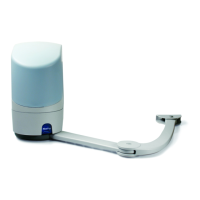
2.7) Assembling the curved arm and mounting the adjustable bracket to the leaf (Fig. 9)
Release the gearmotor.
A:rotate the leaf to the “gate open” position required. Then place the
limit switch on the strike (the arm must be straight) and fasten it
with two Mx25 screws.
B: loosen the screw which fastens the straight arm to the gearmotor,
and fit the protective cover. Insert and tighten the screw which had
been removed.
2.9) Securing the opening stop (Fig. 12)
This is carried out in two steps:
A: lift the cover.
B: insert the release key supplied and turn it clockwise until it stops.
2.8) Releasing the gearmotor from the inside (Fig. 10)
2.4) Mounting the motor bracket to the pillar (Fig. 6)
Use screws which are suitable for the material the pillar is made of. Mount the bracket horizontally.
 Loading...