2.2) Electrical connections
• Carefully follow all the connection instructions. If you
have any doubts do not make experiments but consult
the relevant technical specifications which are also
available on the web site www.niceforyou.com. An incor-
rect connection may be dangerous and cause damage to
the system.
• The TT2L and TT2D control units do not feature any pro-
tection against overload or short circuits on outlets.
Adequate overload protection should be envisaged on
the power supply line, for instance, if a fuse is used its
maximum value should be 5 A for a resistive load of 230
V, or a maximum of 3.15 A in all other cases (inductive
load or 120 V).
3a
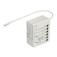
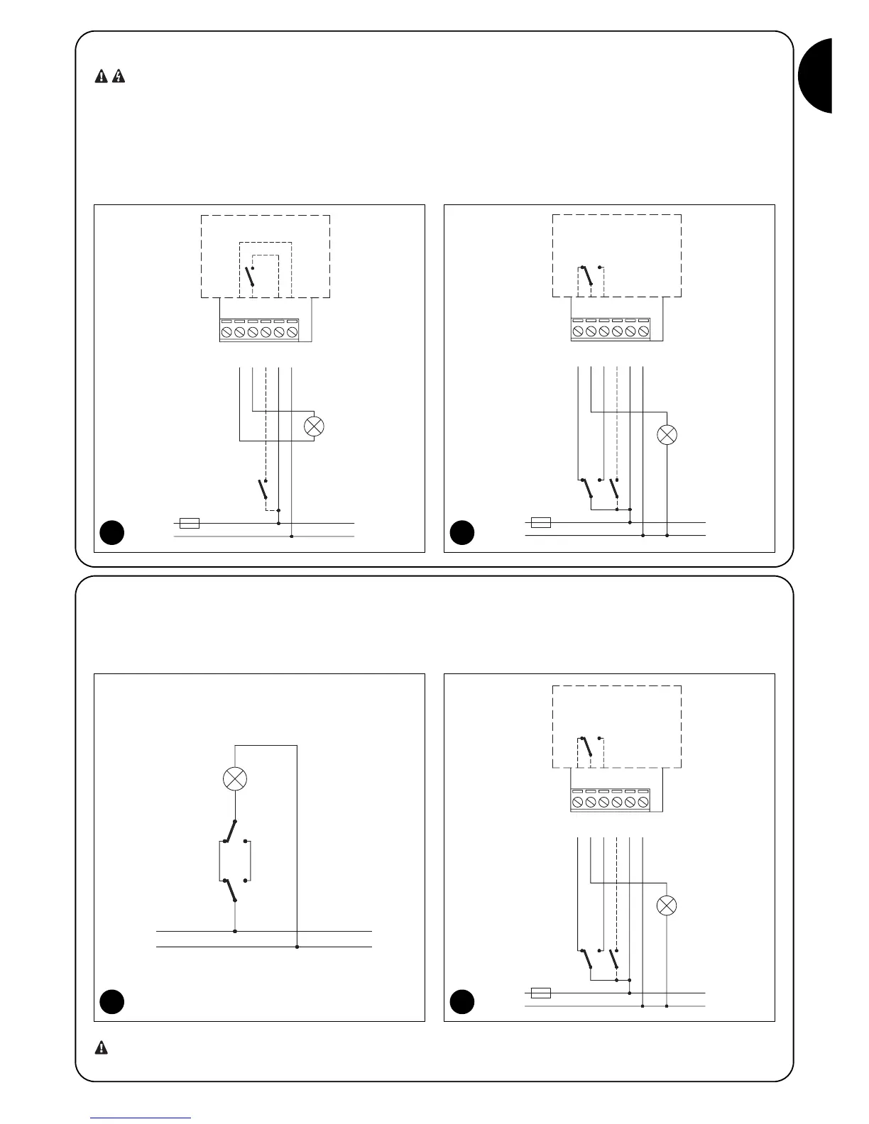
2.2.1) Electrical connection of the device
In the TT2L control unit, the device that has to be controlled must be connected to terminal units 2-3; the device is powered directly by the
control unit.
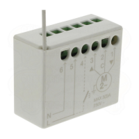
Figure 4a shows an example of operating diagram for the TT2D control unit, where C1 represents a switch in the system, outside TT2D, and
C2 represents the TT2D contact. Figure 4b represents the connections relative to the diagram shown in figure 4a.
4a
 Loading...