EN
English – 3
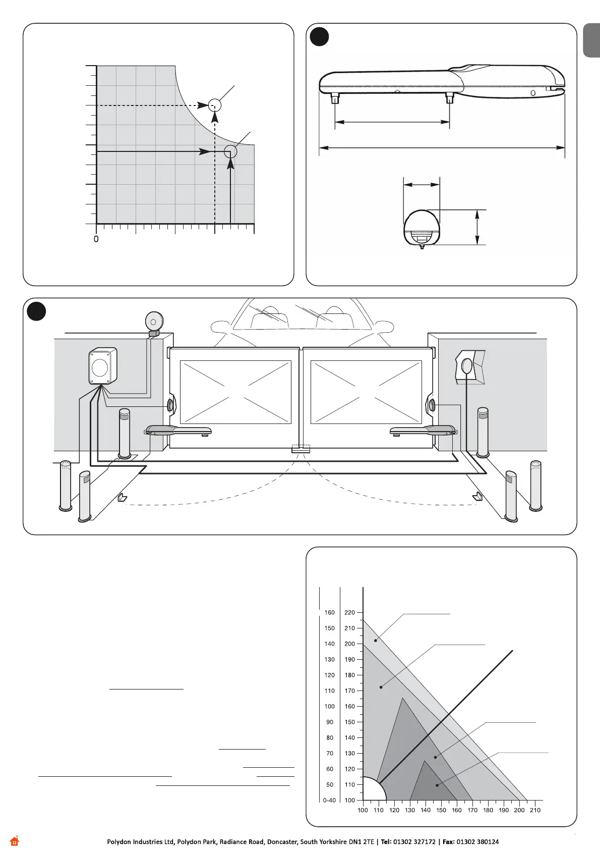
Making reference to fig. 3, decide the approximate position in which to install
each component envisaged by the system and the most appropriate connection
diagram.
Useful components for producing a complete system (fig. 3):
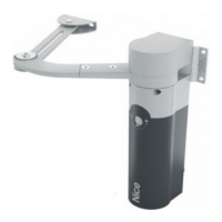
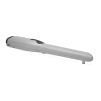
A - Electromechanical gear motors
B - Couple of photocells
C - Couple of stop blocks (in Opening)
D - Columns for photocells
E - Flashing signalling device with incorporated antenna
F - Key selector switch or digital keypad
G - Control unit
3.5 - Installation of fixing brackets and gear motor
3.5.1 - Installation of rear fixing bracket
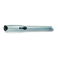
Calculate the position of the rear bracket using graph 2.
This graph serves to establish dimensions A and B and the value of the max-
imum opening angle of the leaf. Important – The values of A and B must be
similar to allow linear movement of the automation.
01. Measure dimension C (fig. 4 / 6) on the fixing side;
02. On graph 2, identify dimension C found and trace a horizontal line
that de-
termines the value of dimension B (*) as shown in the example of fig. 5; the
meeting point with line “r.i.l” (installation line recommended) determines the
value of the angle of maximum opening. From this point, trace a vertical line
as shown in the example of fig. 5 to determine the value of dimension A.
If the angle found does not correspond to the requirements, adapt dimen-
sion A and if necessary dimension B, so they are similar.
03. Before being fixed to the wall the bracket must be sealed to the specific fix-
ing plate (fig. 7); if necessary the bracket can be cut adapting values of di-
2
 Loading...