0
7
8
6
5
4
3
2
1
9
10
11
12
13
14
15
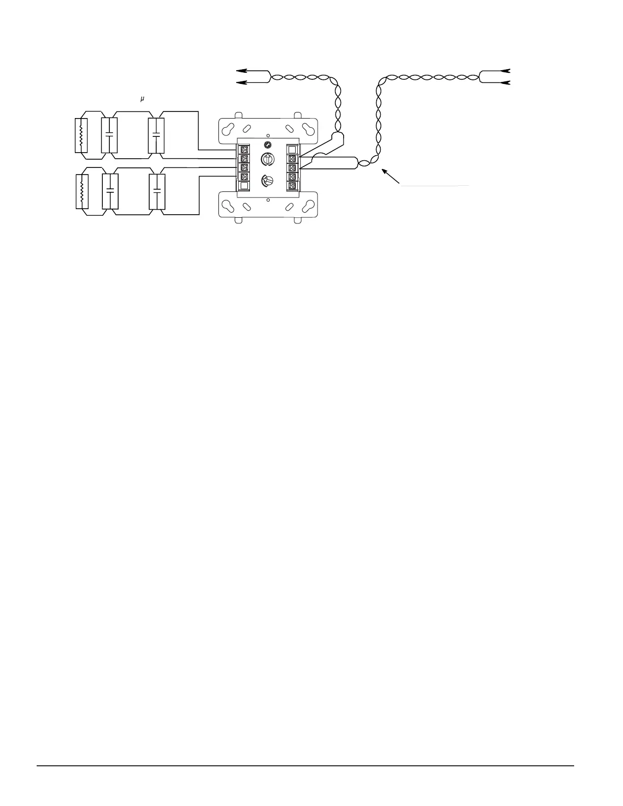
FROM PANEL OR
(+)
(—)
TO NEXT
(+)
(—)
DEVICE
(+)
(—)
MONITOR
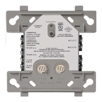
CONNECT MODULES TO LISTED COMPATIBLE
32 VDC MAX.
SHIELDED-TWISTED PAIR
IS RECOMMENDED
NOTIFIER CONTROL PANELS ONLY
PREVIOUS DEVICE
COMMUNICATION LINE
MONITOR A (TERMINALS 6 & 7) RESPONDS AT ADDRESS
SET ON CODE SWITCHES. MONITOR B (TERMINALS 8 & 9)
RESPONDS AT NEXT HIGHER ADDRESS.
ANY NUMBER OF UL LISTED CONTACT CLOSURE
DEVICES MAY BE USED. DO NOT MIX FIRE
ALARM INITIATING, SUPERVISORY, OR SECURITY
DEVICES ON THE SAME INITIATING DEVICE CIRCUIT.
INSTALL CONTACT CLOSURE DEVICES PER
MANUFACTURER’S INSTALLATION INSTRUCTIONS.
47 K EOL
RESISTOR
ELR-47K
MODULE
47 K EOL
RESISTOR
ELR-47K
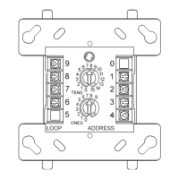
H
L
9
8
7
6
5
4
3
2
1
0
TENS
ONES
ADDRESS
LOOP
0
2
4
6
8
TWO INITIATING DEVICE CIRCUITS (L & H),
EACH POWER LIMITED TO 230 A @ 12VDC MAX.
ALL WIRING SHOWN IS SUPERVISED AND POWER LIMITED
Figure 3. Typical 2-wire initiating circuit conguration, NFPA Style B:
 Loading...