MODULE
FROM PANEL OR
(+)
(–)
TO NEXT
(+)
(–)
DEVICE
(+)
(–)
CONTROL
CONNECT MODULES TO LISTED COMPATIBLE
RELAY COMMON 1
RELAY COMMON 2
NORMALLY CLOSED 1
NORMALLY OPEN 2
NORMALLY CLOSED 2
MODULE DOES NOT SUPERVISE CONTROLLED CIRCUITS
NORMALLY OPEN 1
CONTROL PANELS ONLY
PREVIOUS DEVICE
COMMUNICATION LINE
32 VDC Max.
SHIELDED-TWISTED PAIR
IS RECOMMENDED
9
8
7
6
5
4
3
2
1
0
ADDRESS
LOOP
N500-47-00 2 I56-1170-04
©2001 Notier
All relay switch contacts are shipped as shown in Figure 3, but may have transferred during shipping. To ensure that the switch contacts
are in their correct state, modules must be made to communicate with the panel before connecting circuits controlled by the module.
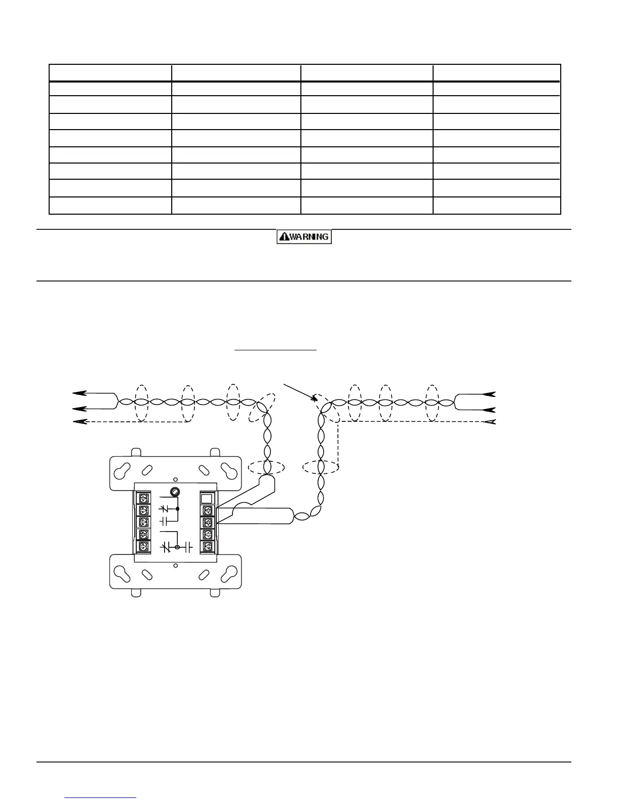
Relay Contact Ratings:
Figure 3. Relay module wiring diagram:
A78-2286-09
CURRENT RATING MAXIMUM VOLTAGE LOAD DESCRIPTION APPLICATION
3 A
2 A
.9 A
.9 A
.5 A
1 A
.5 A
.7 A
30 VDC
30 VDC
110 VDC
125 VAC
30 VDC
30 VDC
125 VAC
75 VAC
Resistive
Resistive
Resistive
Resistive
Inductive (L/R=5ms)
Inductive (L/R=2ms)
Inductive (PF=.35)
Inductive (PF=.35)
Non Coded
Coded
Non Coded
Non Coded
Coded
Coded
Non Coded
Non Coded
IF ANY WIRING TO TERMINALS 3 – 9 IS NONPOWER
LIMITED, THE CB500 BARRIER IS REQUIRED. THE CB500
INCLUDES A NONPOWER LIMITED LABEL, WHICH MUST
BE PLACED OVER THE POWER LIMITED TERMINAL
INFORMATION ON THE NAMEPLATE LABEL.
www.PDF-Zoo.com